Renogy Rover Wiring Diagram: Battery, Solar Panel & Load Connections
The Renogy Rover wiring diagram looks complicated only until you see the pattern: the battery connects first through a fuse, the solar array connects last, and small DC loads sit on the load terminals in between.
This guide walks through the Renogy Rover wiring diagram with battery, step by step, for the Renogy Rover 40A MPPT Solar Charge Controller. You will get wire and fuse sizes, the right way to connect Renogy solar panels together, and where to find the official manual PDFs. A one-page Renogy Rover wiring diagram PDF is included below so you can print it for your battery box or van wall.
I am Abdul Wassay, an electrical engineer with more than 15 years in industrial automation, electrical troubleshooting and renewable-energy design. The specs here come from Renogy’s published Rover 40A documentation, and the wiring practice follows standard DC practice. Always follow your local electrical code and the manual that shipped with your controller.
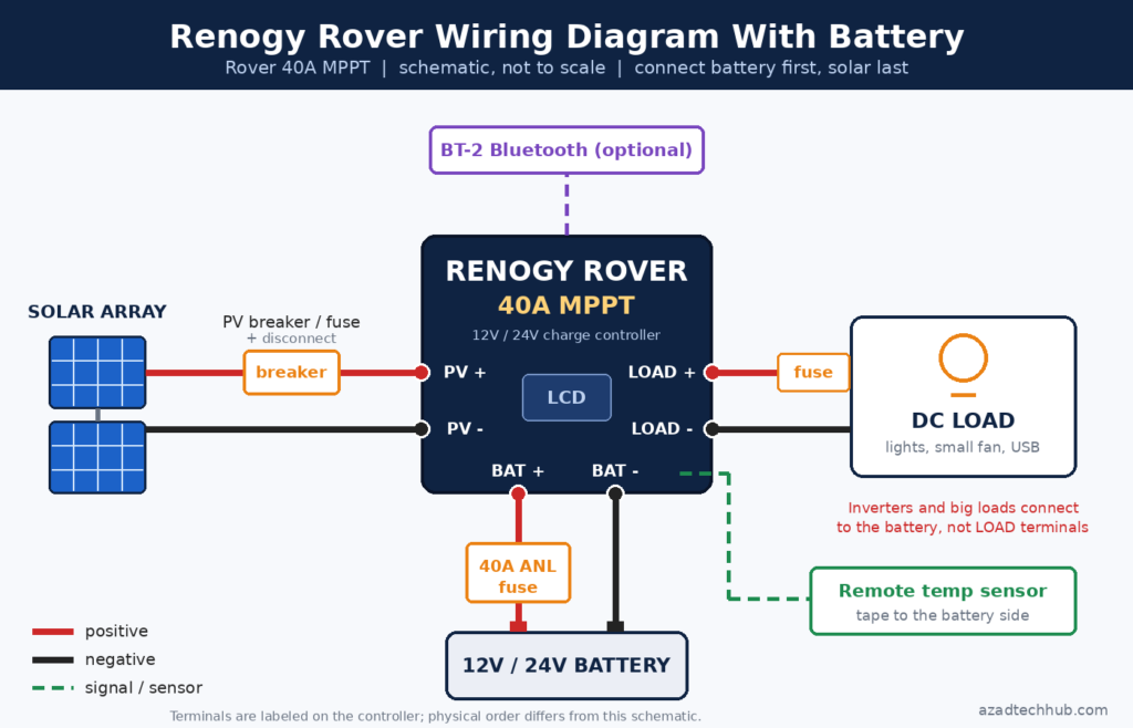
Table of Contents
Table of Contents
What Is the Basic Renogy Rover Wiring Diagram?
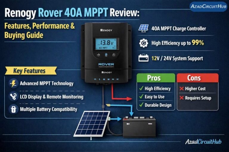
Every Renogy Rover wiring diagram has the same four connections:
- Battery positive and negative go to the BAT terminals, with a 40A fuse in the positive line close to the battery.
- Solar array positive and negative go to the PV terminals, through a breaker or fuse and a disconnect.
- An optional DC load goes to the LOAD terminals (lights, a small fan, a USB charger).
- The remote temperature sensor plugs into its port and is taped to the battery. An optional BT-2 Bluetooth module plugs into the communication port.
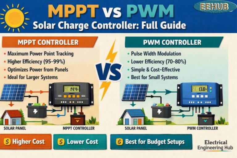
The controller sits in the middle and converts the higher solar panel voltage into the right charging voltage for your battery. That is the whole advantage of MPPT over a basic PWM controller. If you are still choosing a controller, my guide to the best solar charge controller compares MPPT and PWM options side by side.
What You Need Before Following the Renogy Rover Wiring Diagram
- Controller: the Rover 40A (12V/24V auto-detect for non-lithium batteries)
- Fuse: a 40A ANL fuse and holder, which Renogy recommends between the controller and the battery
- Battery cable: copper up to 8 AWG, the largest size the Rover 40A terminals accept
- Solar side: PV wire, a solar-connector-to-controller adapter kit, a PV breaker or fuse, and a disconnect
- Tools: screwdriver, multimeter, wire stripper, crimper and ring terminals
Before buying cable, run your distances through the DC cable size calculator and confirm your panels fit the controller with the solar charge controller sizing calculator. For the theory behind conductor selection, read Cable Sizing for Solar System.

- Superior MPPT Technology: Renogy MPPT Solar Charge Controller achieves a 98% conversion rate&99% tracking efficiency, en…
- All-Weather Solar Charge Controller: Renogy charge controller operates from-40°F to 149°F, with built‑in low‑temp protec…
Renogy Rover Wiring Diagram With Battery: Correct Connection Order
Order matters. Renogy’s own instructions start with the battery and disconnect in the reverse order. Follow this sequence:
- De-energize everything. Open the PV breaker, leave the battery fuse out, and cover the panels if they are in sun.
- Mount the controller on a flat surface with open space around it for heat dissipation. The box includes four mounting brackets.
- Connect the battery. Wire positive to BAT+ and negative to BAT-, then insert the fuse last.
- Set the battery type from the controller buttons. With lithium batteries, set the voltage and type manually before connecting solar, because auto-detect applies only to non-lithium batteries.
- Connect the temperature sensor and tape it to the side of the battery.
- Connect the load, if you use one. Inverters and big loads go straight to the battery, not to the load terminals.
- Connect the solar array last. Check polarity with a multimeter, then close the PV breaker. The PV voltage should appear on the LCD.
- Add the BT-2 module if you want to monitor the system in the Renogy DC Home app.

Running lithium? My guide to the best solar charge controller for LiFePO4 batteries explains charge profiles and sizing.
How to Connect Wire to a Solar Controller
The Rover uses a screw-down hatch terminal. Renogy’s three steps are:
- Loosen the screw above the terminal so the hatch drops.
- Insert the stripped wire into the socket in the hatch. Do not push it into the space below the socket, because a loose connection there damages the terminal.
- Tighten the screw so the hatch rises and clamps the conductor.
The Rover 40A terminals accept wire up to 8 AWG. Strip only enough insulation to fill the terminal and give every wire a firm tug test. Loose DC connections get hot under 40A.
How to Connect Renogy Solar Panels Together: Series vs Parallel
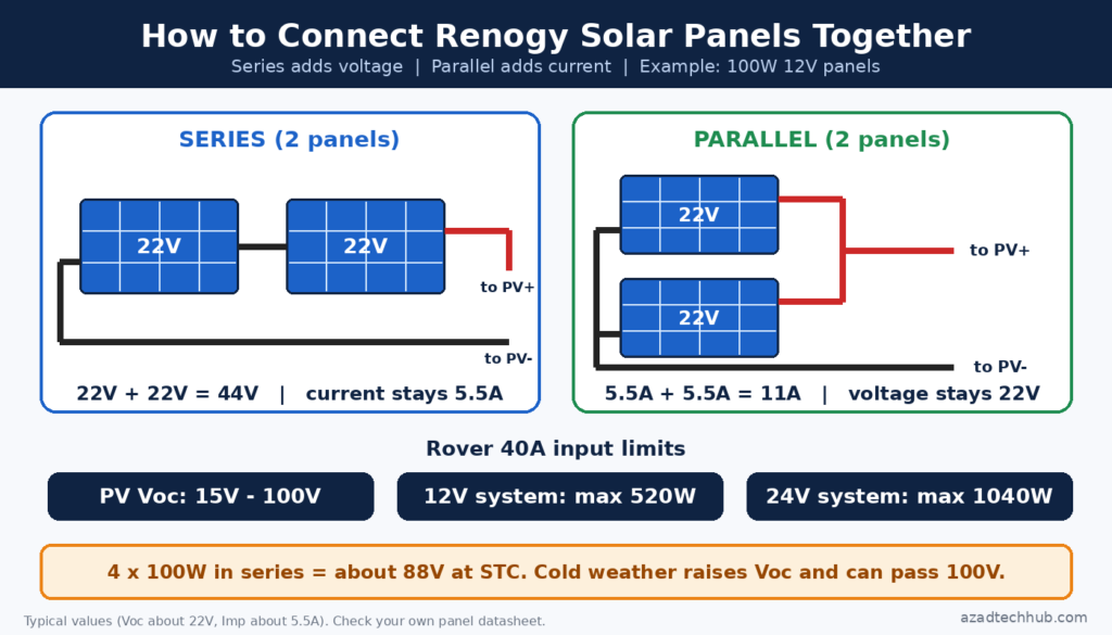
The controller accepts panels in series, in parallel, or in a mix. Your Renogy Rover wiring diagram changes only on the PV side when you switch layouts. The battery and load side stays identical.
| Layout | Voltage | Current | Best for |
|---|---|---|---|
| Series | Adds up | Stays the same | Long runs and thinner wire |
| Parallel | Stays the same | Adds up | Shaded roofs and low-voltage arrays |
| Series-parallel | Adds per string | Adds per string | Larger arrays |
The Rover 40A limits are what matter. Solar input voltage (Voc) must stay between 15V and 100V, and maximum PV power is 520W on a 12V system or 1,040W on a 24V system.
Example with four 100W 12V panels (typical Voc about 22V, Imp about 5.5A; use your own datasheet):
- Two in series, two strings in parallel: about 44V and 11A, 400W total. This fits the 520W limit on 12V.
- All four in series: about 88V at standard conditions. Cold mornings raise Voc, so this can exceed 100V and damage the controller.
Use the solar panel size calculator by load to match panel wattage to your daily energy needs.
Wire and Fuse Sizes for Your Renogy Rover Wiring Diagram
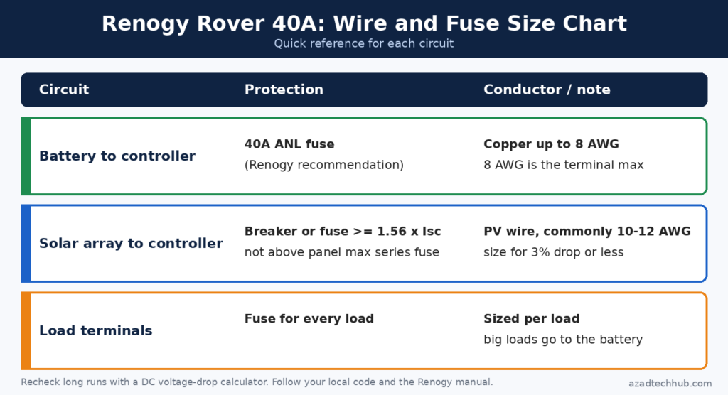
| Circuit | Protection | Conductor | Note |
|---|---|---|---|
| Battery to controller | 40A ANL fuse (Renogy recommendation) | Copper up to 8 AWG | 8 AWG is the terminal maximum. Keep the run short. |
| Solar array to controller | Breaker or fuse of at least 1.56 x Isc, not above the panel’s max series fuse rating | PV wire, commonly 10 to 12 AWG on short runs | Size for no more than 3% voltage drop |
| Load terminals | Fuse for each load | Sized per load | Big loads go directly to the battery |
The Rover has internal protections, but they do not replace external overcurrent protection. For fuse and breaker rules, see my guide to NEC overcurrent protection. For longer runs, recheck every conductor with the DC cable size calculator.
Renogy Rover Wiring Diagram PDF Download
I made a one-page Renogy Rover wiring diagram PDF with the connection order, the wire and fuse table, and the series and parallel limits. Print it and keep it with your system.
Renogy Rover Manual PDF Free Download
The official manual is free from Renogy. The Rover Li 40A download page lists the Rover 40A manual, which also answers the “renogy rover 40 amp mppt charge controller manual pdf” search. The Rover product page also carries the warranty PDF and the DC Home app manual.
Rover 60A and Other Renogy Wiring Diagram PDFs
The Rover 60A manual is on the Rover 60 product page under its downloads section. If you are deciding between sizes, read Renogy Rover 40A vs 60A first. Other Renogy controllers follow the same battery-first logic, but terminal sizes and limits differ, so always check that model’s own manual.
The Renogy 50A DC-DC charger is a different product. It charges from an alternator, not from solar panels, so do not use a Rover diagram for it. Get its manual from its own product page.
Common Renogy Rover Wiring Mistakes
- Connecting solar before the battery, or disconnecting in the wrong order.
- Skipping the battery fuse because the controller has “protection”.
- Wiring panels in series until cold-weather Voc passes 100V.
- Running an inverter from the load terminals instead of the battery.
- Leaving the temperature sensor off the battery.
- Pushing the wire into the space under the hatch, so it never clamps.
Most faults I see in a Renogy Rover wiring diagram that someone sends for review come from one of these six.
Is the Rover 40A the Right Controller for Your System?
The Rover 40A suits 12V and 24V systems up to 520W or 1,040W of panels. For a full breakdown, read my Renogy Rover 40A MPPT review. Building a mobile setup? See the best MPPT charge controller for van life. Sizing for a bigger bank? See the best MPPT charge controller for a 12V 200Ah battery. If you are comfortable with the wiring above, you can check the current price of the Renogy Rover 40A on Amazon.
- Superior MPPT Technology: Renogy MPPT Solar Charge Controller achieves a 98% conversion rate&99% tracking efficiency, en…
- All-Weather Solar Charge Controller: Renogy charge controller operates from-40°F to 149°F, with built‑in low‑temp protec…
More reviews and comparisons are in the Solar Charge Controller Reviews category. For a whole-system plan, use the off-grid solar system design guide.
Frequently Asked Questions
How to connect Renogy solar panels together?
Wire them in series, parallel or series-parallel, then bring one positive and one negative lead to the PV terminals. Keep total Voc under 100V in cold weather and total panel power under 520W on 12V or 1,040W on 24V.
What is the basic Renogy Rover wiring diagram?
Battery through a 40A fuse to the BAT terminals, solar array through a breaker to the PV terminals, optional load to the LOAD terminals, and the temperature sensor on the battery. Connect the battery first and the solar array last.
Where can I find the manual for the Renogy Rover 60 amp MPPT charge controller?
On the Rover 60A product page at Renogy under the downloads section, or through Renogy’s support downloads. The 60A manual covers its own limits and terminals.
How to connect wire to a solar controller?
Loosen the terminal screw, insert the stripped wire into the socket in the hatch, then tighten the screw to clamp it. The Rover 40A accepts up to 8 AWG.
Is the Renogy Rover manual PDF free to download?
Yes. Renogy publishes the manual, warranty and DC Home app manual on its product and support pages at no charge.
Can I use this Renogy Rover wiring diagram for a 24V system?
Yes. The wiring layout is the same. The Rover auto-detects 12V or 24V for non-lithium batteries, and the PV limit rises to 1,040W on 24V.
Conclusion
Follow the Renogy Rover wiring diagram in order: battery with a 40A fuse first, load second, solar array last. Keep cold-weather Voc under 100V, size wire for voltage drop, and never skip external fuses. Download the Renogy Rover wiring diagram PDF, keep it near the controller, and use the official Renogy manual for your exact model. When you are ready, the Renogy Rover 40A MPPT Solar Charge Controller is a solid fit for 12V and 24V systems.
Get new guides in your feed. Follow Electrical Insights on LinkedIn for new electrical standards guides, calculators and design tips from Azad Circuit Hub.