Phase to Phase Clearance for ANSI/IEEE Transmission Voltages (69-500 kV)
Phase to phase clearance is one of the most important electrical design requirements in transmission lines and substations. Adequate spacing between energized conductors prevents flashover, reduces the risk of phase-to-phase faults, and provides enough insulation distance during normal and abnormal operating conditions.
The required distance depends on system voltage, insulation coordination, air density, conductor movement, switching surges, lightning impulses, and the arrangement of the equipment. For this reason, there is no single clearance that applies to every 69 kV to 500 kV installation.
This guide explains Phase to Phase Clearance for ANSI/IEEE Transmission Voltages and provides practical reference values for 69 kV, 115 kV, 138 kV, 161 kV, 230 kV, 345 kV, and 500 kV systems.
Important: The values below are engineering reference ranges commonly encountered in North American transmission design. Final dimensions should be checked against the applicable ANSI/IEEE standards, NESC requirements, utility construction standards, insulation coordination study, and site altitude.
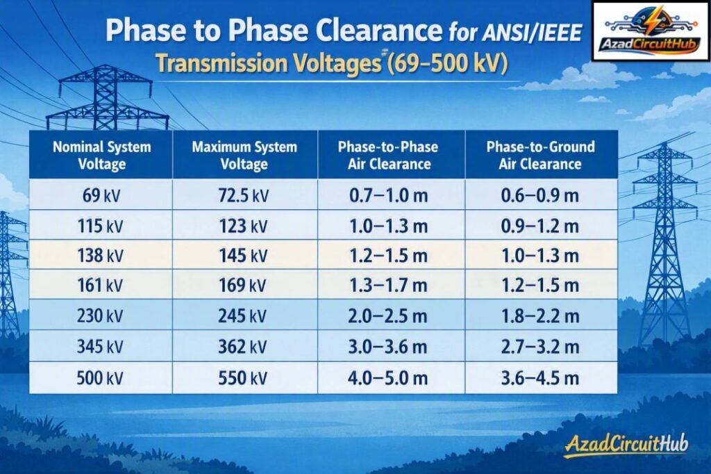
Table of Contents
Table of Contents
Quick Phase Clearance Chart for 69 kV to 500 kV
The following table provides useful preliminary design ranges for air-insulated outdoor transmission equipment and line arrangements.
| Nominal System Voltage | Typical Maximum System Voltage | Approx. Phase-to-Phase Air Clearance | Approx. Phase-to-Ground Air Clearance |
|---|---|---|---|
| 69 kV | 72.5 kV | 0.7–1.0 m | 0.6–0.9 m |
| 115 kV | 123 kV | 1.0–1.3 m | 0.9–1.2 m |
| 138 kV | 145 kV | 1.2–1.5 m | 1.0–1.3 m |
| 161 kV | 169 kV | 1.3–1.7 m | 1.2–1.5 m |
| 230 kV | 245 kV | 2.0–2.5 m | 1.8–2.2 m |
| 345 kV | 362 kV | 3.0–3.6 m | 2.7–3.2 m |
| 500 kV | 550 kV | 4.0–5.0 m | 3.6–4.5 m |
These are preliminary engineering ranges, not universal code minimums. The final clearance can be larger where high altitude, contamination, switching overvoltage, conductor swing, or utility-specific requirements apply.
Phase to Phase Clearance for ANSI/IEEE Transmission Voltages
Phase to Phase Clearance for ANSI/IEEE Transmission Voltages increases significantly as the operating voltage rises. A 69 kV line therefore requires much less conductor spacing than a 500 kV transmission system.
The main purpose of phase spacing is to maintain sufficient electrical withstand capability through air. The clearance must also account for mechanical movement caused by wind, temperature, ice, short-circuit forces, and conductor sag.
| Voltage Level | Common Application | Preliminary Phase Spacing |
|---|---|---|
| 69 kV | Subtransmission/transmission | 0.7–1.0 m |
| 115 kV | Transmission | 1.0–1.3 m |
| 138 kV | Transmission | 1.2–1.5 m |
| 161 kV | Transmission | 1.3–1.7 m |
| 230 kV | High-voltage transmission | 2.0–2.5 m |
| 345 kV | Extra-high-voltage transmission | 3.0–3.6 m |
| 500 kV | Extra-high-voltage transmission | 4.0–5.0 m |
For a preliminary layout, engineers normally start with the electrical clearance and then check the mechanical envelope. The conductor’s maximum swing position must not reduce the final separation below the required value.
69 kV Phase to Phase and Phase to Ground Clearance
For a 69 kV system, a preliminary phase-to-phase spacing of approximately 0.7 to 1.0 m is commonly used for outdoor transmission arrangements. Phase-to-ground clearance is generally somewhat lower, often around 0.6 to 0.9 m depending on the equipment and insulation design.
69 kV Phase to Phase Clearance
The 69 kV phase-to-phase distance must accommodate normal operating voltage as well as transient overvoltages. Line geometry, insulator strings, crossarm configuration, and conductor movement can change the required spacing.
69 kV Phase to Ground Clearance
For outdoor substations, the phase-to-ground distance must also consider nearby structures, steelwork, transformer tanks, gantries, and grounded equipment.
115 kV Phase to Phase and Phase to Ground Clearance
A 115 kV system commonly uses approximately 1.0 to 1.3 m of preliminary phase-to-phase air spacing. A preliminary phase-to-ground distance may fall around 0.9 to 1.2 m.
| Parameter | Typical Preliminary Range |
|---|---|
| 115 kV phase-to-phase | 1.0–1.3 m |
| 115 kV phase-to-ground | 0.9–1.2 m |
| Typical application | Transmission/substation |
| Main checks | Switching impulse, lightning impulse, conductor movement |
The actual dimensions can increase at high elevations because lower air density reduces the dielectric strength of the air gap.
138 kV Phase to Phase and Phase to Ground Clearance
For 138 kV transmission systems, preliminary phase-to-phase spacing is commonly in the range of 1.2 to 1.5 m. Phase-to-ground spacing may be approximately 1.0 to 1.3 m.
A 138 kV substation layout should not be based only on nominal voltage. The engineer should also consider the maximum system voltage and selected insulation level.
161 kV Phase to Phase and Phase to Ground Clearance
The preliminary phase-to-phase clearance for 161 kV equipment is commonly around 1.3 to 1.7 m, while phase-to-ground clearance may be approximately 1.2 to 1.5 m.
161 kV yards can have substantial conductor movement, particularly where flexible bus conductors are used. The clearance therefore needs to be checked under both static and dynamic conditions.
230 kV Phase to Phase and Phase to Ground Clearance
230 kV transmission equipment requires substantially greater air gaps. A preliminary phase-to-phase distance of approximately 2.0 to 2.5 m is commonly encountered, with phase-to-ground spacing around 1.8 to 2.2 m.
| 230 kV Design Check | Typical Consideration |
|---|---|
| Phase-to-phase | 2.0–2.5 m |
| Phase-to-ground | 1.8–2.2 m |
| Switching surge | Important |
| Lightning impulse | Important |
| Conductor swing | Must be checked |
| Altitude correction | Required where applicable |
At this voltage level, switching overvoltages become an important part of insulation coordination. Simply scaling a lower-voltage clearance by voltage ratio is not a reliable design method.
345 kV Phase to Phase and Phase to Ground Clearance
For 345 kV systems, preliminary phase-to-phase spacing is commonly about 3.0 to 3.6 m. Phase-to-ground clearance can be approximately 2.7 to 3.2 m.
The physical arrangement becomes particularly important at this voltage. Busbar configuration, disconnect switch operation, flexible conductor movement, and maintenance zones can all influence the final substation dimensions.
For transmission lines, the conductor bundle arrangement and tower geometry also affect the phase spacing. Engineers should check the complete conductor envelope rather than relying only on the nominal static position.
500 kV Phase to Phase and Phase to Ground Clearance
500 kV transmission systems require large electrical clearances because of their high insulation and transient-voltage requirements. A preliminary phase-to-phase range of approximately 4.0 to 5.0 m is often used for initial outdoor layout studies, while phase-to-ground spacing may be approximately 3.6 to 4.5 m.
| 500 kV Parameter | Preliminary Range |
|---|---|
| Phase-to-phase | 4.0–5.0 m |
| Phase-to-ground | 3.6–4.5 m |
| Conductor bundle | Commonly used |
| Switching surge | Critical design consideration |
| Altitude correction | Important |
| Utility standard | Must be verified |
Extra-high-voltage designs require detailed insulation coordination. The final spacing may differ considerably from a preliminary table because switching impulse withstand, arrester protection, line configuration, and site conditions all influence the design.
What Determines Transmission Phase Clearance?
Phase spacing is not determined by nominal voltage alone. Several engineering factors must be considered before selecting the final dimension.
| Design Factor | Effect on Clearance |
|---|---|
| System voltage | Higher voltage generally requires greater spacing |
| Maximum system voltage | Used in insulation coordination |
| Lightning impulse | Can increase required air distance |
| Switching impulse | Particularly important at EHV |
| Altitude | Higher altitude reduces air insulation strength |
| Pollution | May affect insulation selection |
| Wind | Causes conductor swing |
| Temperature | Changes conductor sag and position |
| Ice loading | Changes mechanical geometry |
| Short-circuit forces | Can move conductors |
| Utility standard | May specify larger minimum values |
The practical design objective is to maintain the required insulation margin under the most unfavorable credible operating condition.
Phase-to-Phase vs Phase-to-Ground Clearance
Phase-to-phase and phase-to-ground clearances serve different purposes. Phase-to-phase spacing prevents an electrical arc between two energized phases, while phase-to-ground clearance prevents an energized conductor from flashing over to grounded structures or equipment.
| Clearance Type | Protected Against | Typical Design Location |
|---|---|---|
| Phase-to-phase | Phase fault/flashover | Between conductors |
| Phase-to-ground | Ground flashover | Conductor to tower/steel |
| Conductor-to-structure | Electrical contact | Substations and lines |
| Bus-to-bus | Bus fault | Outdoor switchyards |
| Terminal-to-ground | Flashover | Transformer and breaker terminals |
In many outdoor substations, phase-to-ground dimensions are smaller than phase-to-phase dimensions, but this should never be assumed without checking the applicable insulation coordination requirements.
How Altitude Affects Phase Clearance
Air becomes less dense as elevation increases. Because air has lower dielectric strength at high altitude, an air clearance that is acceptable near sea level may require correction at a mountainous site.
For this reason, an insulation coordination study should include the site elevation. A utility may also specify a standard altitude correction method.
A simple preliminary layout should therefore identify:
- Site elevation.
- Maximum operating voltage.
- Basic insulation level.
- Switching impulse withstand level.
- Lightning impulse withstand level.
- Pollution and environmental conditions.
- Required conductor movement.
The final dimensions should then be confirmed using the applicable engineering standard and utility specification.
Transmission Line Phase Spacing vs Substation Clearance
Transmission towers and substations do not necessarily use the same spacing philosophy. Transmission line phase spacing is strongly influenced by conductor swing, tower geometry, sag, wind, and line insulation.
Substations have additional requirements because equipment terminals, disconnect switches, busbars, transformers, breakers, and grounded structures are located close together.
| Installation | Major Clearance Considerations |
|---|---|
| Transmission line | Wind swing, sag, tower geometry |
| Outdoor substation | Equipment arrangement and maintenance |
| AIS switchyard | Busbars, breakers and disconnectors |
| Transformer bay | Bushings, terminals and grounded tank |
| Line bay | Incoming conductor and gantry |
| GIS | Enclosed insulation system |
For low-voltage and medium-voltage assembly applications, a separate clearance assessment is required. For more information on equipment-level spacing, see our guide to phase to phase clearance as per iec 61439.
Phase Clearance and Insulation Coordination
Clearance should be coordinated with the selected insulation system. The engineer normally considers the relationship between system voltage, temporary overvoltages, lightning impulses, switching impulses, and protective devices.
Surge arresters can reduce the voltage stress seen by equipment, but they do not eliminate the need for appropriate air clearance.
A useful design sequence is:
- Determine the highest system voltage.
- Establish the required insulation withstand levels.
- Identify lightning and switching overvoltages.
- Select suitable surge protection.
- Determine the required air distances.
- Apply altitude and environmental corrections.
- Check mechanical conductor movement.
- Verify the final layout against the applicable standard.
Common Transmission Voltage Clearance Summary
| Voltage | Phase-to-Phase | Phase-to-Ground |
|---|---|---|
| 69 kV | 0.7–1.0 m | 0.6–0.9 m |
| 115 kV | 1.0–1.3 m | 0.9–1.2 m |
| 138 kV | 1.2–1.5 m | 1.0–1.3 m |
| 161 kV | 1.3–1.7 m | 1.2–1.5 m |
| 230 kV | 2.0–2.5 m | 1.8–2.2 m |
| 345 kV | 3.0–3.6 m | 2.7–3.2 m |
| 500 kV | 4.0–5.0 m | 3.6–4.5 m |
These figures are useful for preliminary planning and comparison. They should not replace the detailed clearance requirements of the governing standard or transmission utility.
When working on an existing switchgear or electrical assembly, our detailed guide on phase to phase clearance as per iec 61439 can help with the separate IEC 61439 equipment-clearance considerations.
How to Calculate Phase-to-Phase Clearance
A practical clearance calculation starts with the required insulation withstand level rather than simply using the nominal voltage.
The general engineering process is:
System voltage → insulation level → overvoltage assessment → required air distance → environmental correction → mechanical clearance check
For a preliminary project estimate, designers can compare the required voltage level with established utility construction standards. For a final design, the air gap should be verified using the applicable insulation coordination procedure.
For quick preliminary checks across different electrical systems, use a Phase to Phase Clearance Calculator and then verify the calculated value against the project specification and applicable standard.
Standards Commonly Consulted
The exact standard depends on whether the project involves a transmission line, outdoor substation, switchgear, or another type of electrical installation.
| Standard/Reference | Typical Relevance |
|---|---|
| ANSI/IEEE standards | Electrical equipment and system design |
| IEEE 1313.1 | Insulation coordination principles |
| IEEE 1313.2 | Application guidance for insulation coordination |
| IEEE 516 | Live-line working practices and electrical clearances |
| NESC | Overhead supply and communication line safety |
| ANSI/IEEE C37 series | High-voltage switchgear and equipment |
| Utility construction standards | Project-specific minimum dimensions |
| IEC 60071 series | Insulation coordination where IEC standards apply |
The applicable edition and project requirements should always be confirmed before using a published clearance value for construction.
Frequently Asked Questions
What is the phase-to-phase clearance for 69 kV?
A preliminary outdoor design value for 69 kV is approximately 0.7 to 1.0 m phase-to-phase. The final clearance depends on insulation level, altitude, conductor movement, equipment arrangement, and the applicable utility or electrical standard.
What is the phase-to-ground clearance for 138 kV?
A preliminary 138 kV phase-to-ground air clearance is commonly around 1.0 to 1.3 m. Actual substation or transmission-line dimensions must be confirmed through insulation coordination and the governing project standard.
What is the phase-to-phase clearance for 230 kV?
For preliminary outdoor transmission design, approximately 2.0 to 2.5 m may be used as a reference range. Switching impulse, lightning impulse, conductor movement, altitude, and utility requirements can result in a different final value.
What is the phase-to-phase clearance for 500 kV?
A preliminary 500 kV phase-to-phase air spacing is often around 4.0 to 5.0 m in outdoor transmission applications. EHV projects require detailed insulation coordination, so the final dimension should not be selected from a generic table alone.
Does altitude affect transmission phase clearance?
Yes. Higher altitude reduces air density and therefore reduces the dielectric strength of an air gap. Transmission and substation designs at elevated locations may require increased clearances or appropriate altitude correction factors.
Final Takeaway
Phase to Phase Clearance for ANSI/IEEE Transmission Voltages must be selected as part of the overall insulation coordination and mechanical design process. The required distance increases substantially from 69 kV through 500 kV, but nominal voltage alone does not determine the final dimension.
For preliminary planning, the reference ranges in this guide provide a useful starting point for 69 kV, 115 kV, 138 kV, 161 kV, 230 kV, 345 kV, and 500 kV systems. Before construction, always verify the final phase-to-phase and phase-to-ground distances against the applicable ANSI/IEEE or NESC requirements, utility standards, equipment specifications, site altitude, and project insulation coordination study.
Get new guides in your feed. Follow Electrical Insights on LinkedIn for new electrical standards guides, calculators and design tips from Azad Circuit Hub.
#PhaseToPhaseClearance, #ANSIIEEE, #TransmissionVoltages, #HighVoltageClearance, #TransmissionLines, #SubstationClearance, #IEEEStandards, #ElectricalEngineering, #HighVoltage, #PowerSystems