
Phase to Phase Clearance as per NEC / NFPA 70E
Understanding electrical clearances is essential when designing, installing, inspecting, and maintaining switchboards, panelboards, busbars, control panels, and other energized equipment. However, one important point is often missed: NEC and NFPA 70E do not provide one universal phase-to-phase clearance value that applies to every voltage level and equipment type.
The required spacing depends on the equipment construction, voltage, insulation system, enclosure, listed product requirements, and applicable electrical standard. This guide explains how to interpret phase spacing under NEC and NFPA 70E and how it differs from working space and approach boundaries.
Quick Reference: Phase to Phase Clearance as per NEC / NFPA 70E
| Requirement | NEC / NFPA 70E Reference | What It Controls |
|---|---|---|
| Phase-to-phase conductor spacing | Equipment-specific requirements and listing standards | Separation between energized phases |
| Working space | NEC 110.26 | Space around electrical equipment for operation and maintenance |
| Guarding | NEC 110.27 | Protection from accidental contact |
| Installation according to listing | NEC 110.3(B) | Equipment must be installed according to its instructions |
| Shock approach boundaries | NFPA 70E Article 130 | Distance from exposed energized conductors |
| Arc-flash boundary | NFPA 70E Article 130 | Distance at which an arc-flash hazard may exist |
| Switchgear construction | Applicable product standard | Internal electrical clearances and construction |
| Low-voltage assemblies | UL/IEC equipment standards | Internal insulation and spacing requirements |
For designers, the key principle is that Phase to Phase Clearance as per NEC is not normally selected from a single NEC table. The applicable equipment standard and manufacturer’s listing requirements must also be considered.
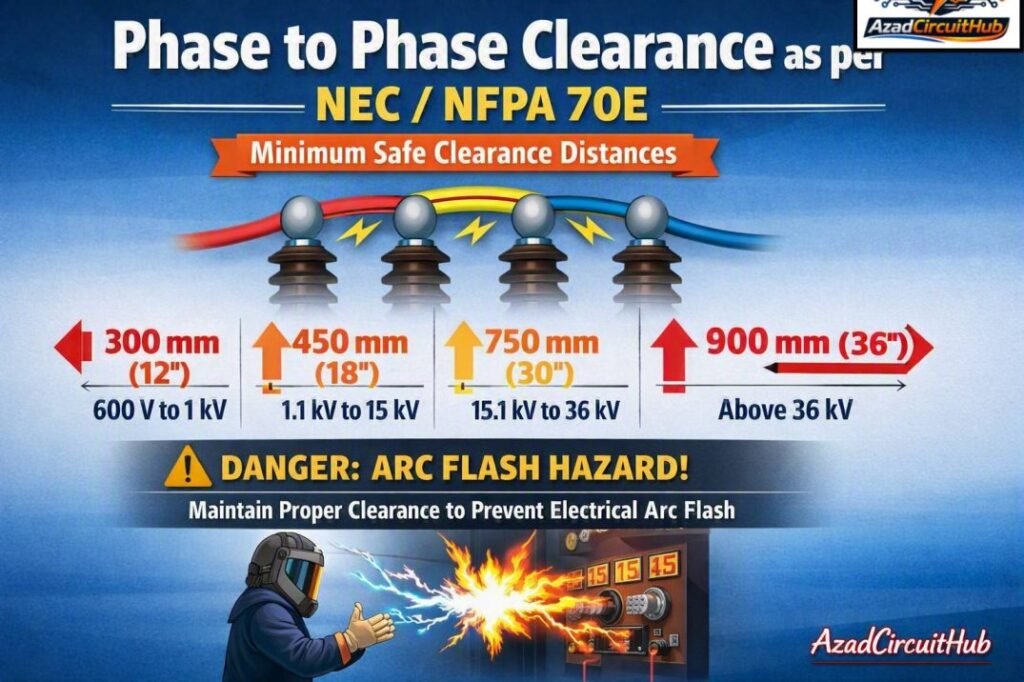
Table of Contents
Table of Contents
What Is Phase-to-Phase Clearance?
Phase-to-phase clearance is the shortest distance through air between two conductive parts belonging to different electrical phases.
For example, in a three-phase system, the clearance between L1 and L2 is a phase-to-phase clearance. The same concept applies between L2 and L3 or L3 and L1.
| Term | Meaning |
|---|---|
| Clearance | Shortest distance through air between conductive parts |
| Creepage distance | Shortest distance along an insulating surface |
| Phase-to-phase spacing | Separation between conductors of different phases |
| Phase-to-ground clearance | Air distance between a live conductor and grounded metal |
| Working space | Accessible space in front of electrical equipment |
| Approach boundary | NFPA 70E boundary based on shock hazard |
Clearance and creepage should not be treated as interchangeable terms. Clearance mainly addresses dielectric breakdown through air, while creepage considers tracking along an insulating surface.
Does the NEC Specify a Minimum Phase-to-Phase Clearance?
This is one of the most common questions surrounding Phase to Phase Clearance as per NEC.
The NEC does not establish one universal phase-to-phase air gap for all electrical equipment. Instead, requirements are distributed across installation rules, equipment requirements, product standards, and listing provisions.
NEC 110.3(B) is particularly important because listed or labeled equipment must be installed and used in accordance with instructions included in the listing or labeling.
This means the correct spacing inside a listed switchboard, panelboard, switchgear assembly, or control panel may be determined by the equipment’s construction standard and manufacturer’s design rather than by a simple NEC clearance chart.
Important NEC Requirements
| NEC Section | General Purpose |
|---|---|
| NEC 110.3(B) | Installation and use according to listing and labeling |
| NEC 110.26 | Spaces about electrical equipment |
| NEC 110.27 | Guarding of live parts |
| NEC 110.14 | Electrical connections and terminations |
| NEC 408 | Switchboards, switchgear, and panelboards |
| NEC 409 | Industrial control panels |
Therefore, when checking Phase to Phase Clearance as per NEC, engineers should first identify the equipment category and its applicable product standard.
NEC 110.26 Is Not Phase-to-Phase Clearance
A frequent design mistake is using NEC 110.26 as an internal conductor-spacing requirement.
NEC 110.26 primarily addresses working space around electrical equipment. It helps ensure that electricians have sufficient room to inspect, operate, maintain, and work on equipment.
Typical working-space dimensions depend on voltage, conditions, and equipment configuration.
| Requirement | Typical NEC Consideration |
|---|---|
| Width | Generally at least 30 in. or equipment width, whichever is greater |
| Depth | Depends on voltage and condition |
| Headroom | Minimum requirements apply |
| Dedicated space | Required for certain indoor electrical equipment |
| Access | Equipment must be readily accessible for operation and maintenance |
These dimensions are not the same as internal phase-to-phase conductor spacing.
NFPA 70E and Electrical Approach Boundaries
NFPA 70E approaches the issue from a worker-safety perspective. It establishes shock protection boundaries and arc-flash requirements rather than prescribing a universal internal busbar spacing.
For exposed energized electrical conductors, NFPA 70E uses approach boundaries based on the system voltage and shock hazard.
| NFPA 70E Concept | Purpose |
|---|---|
| Limited Approach Boundary | Restricts unqualified persons from approaching exposed energized conductors |
| Restricted Approach Boundary | Provides additional protection for qualified workers |
| Arc-Flash Boundary | Identifies the distance at which an arc-flash hazard exists |
| Prohibited approach | Historical terminology; current requirements should be checked against the applicable edition |
The NFPA 70E approach distance is measured from an exposed energized electrical conductor or circuit part. It should not be confused with the physical spacing between two phases inside electrical equipment.
Phase-to-Phase Clearance vs NFPA 70E Approach Distance
The difference becomes clearer when the two requirements are compared.
| Feature | Phase-to-Phase Clearance | NFPA 70E Approach Boundary |
|---|---|---|
| Primary concern | Electrical insulation and dielectric strength | Worker shock protection |
| Location | Between conductive parts | Between worker and energized parts |
| Determined by | Equipment design and applicable standards | Voltage and shock hazard |
| Universal value? | No | No |
| Applies to workers? | Indirectly | Directly |
| Related to arc flash? | Can affect equipment performance | Directly addressed by NFPA 70E |
Thus, increasing the physical distance between two phases does not automatically establish compliance with NFPA 70E.
Phase Spacing in Switchboards and Switchgear
Switchboards, switchgear, panelboards, and industrial control panels require careful attention because internal busbars can carry high fault currents.
The designer should consider:
- System voltage
- Insulation type
- Available fault current
- Short-circuit withstand rating
- Busbar configuration
- Equipment listing
- Pollution and environmental conditions
- Temperature
- Altitude
- Manufacturer requirements
- Applicable UL or IEC product standard
For example, a listed switchgear assembly may have factory-engineered internal clearances that should not be modified in the field.
When designing IEC-based assemblies, it is also useful to understand phase to phase clearance as per iec 61439, particularly when comparing low-voltage assembly requirements with NEC-based installations.
Why Voltage Matters
Higher voltage generally creates greater insulation stress. However, voltage alone does not provide enough information to determine a safe conductor spacing.
| Design Factor | Effect on Clearance |
|---|---|
| Rated voltage | Influences insulation requirements |
| Impulse withstand voltage | Influences required dielectric spacing |
| Pollution degree | Can affect insulation design |
| Altitude | Reduced air density can affect dielectric strength |
| Material group | Important for creepage calculations |
| Enclosure design | Influences environmental exposure |
| Overvoltage category | Affects insulation coordination |
| Equipment standard | Establishes applicable construction requirements |
This is why copying a clearance value from another installation can produce an incorrect design.
Clearance and Creepage: What Is the Difference?
Clearance is measured through air. Creepage is measured along the surface of an insulating material.
For example, two copper busbars may have a 10 mm air gap between them. If an insulating barrier is installed between the conductors, the relevant creepage path may be substantially longer than the direct air gap.
| Parameter | Measurement Path | Main Concern |
|---|---|---|
| Clearance | Through air | Flashover and dielectric breakdown |
| Creepage | Along insulation surface | Tracking and surface leakage |
| Insulation thickness | Through solid insulation | Dielectric withstand |
Both parameters may be important when designing electrical assemblies.
Practical Design Checklist
Before approving phase spacing in electrical equipment, use the following checklist:
- Identify the system voltage and frequency.
- Identify the equipment type.
- Check the equipment listing and manufacturer’s instructions.
- Determine the applicable UL, IEC, or other product standard.
- Verify clearance and creepage requirements.
- Consider pollution, altitude, and environmental conditions.
- Check the equipment short-circuit rating.
- Verify phase-to-ground as well as phase-to-phase spacing.
- Confirm barriers and insulation are properly installed.
- Apply NFPA 70E requirements separately for worker protection.
For systems designed around IEC assemblies, compare the equipment construction requirements with phase to phase clearance as per iec 61439 to understand where IEC and NEC approaches differ.
Common Mistakes to Avoid
Several clearance-related mistakes occur repeatedly in electrical installations.
| Mistake | Why It Is a Problem |
|---|---|
| Using one clearance value for every voltage | Equipment requirements vary |
| Treating working space as conductor spacing | They address different hazards |
| Using NFPA 70E approach distance as busbar spacing | Approach boundaries protect workers |
| Ignoring creepage | Surface tracking may remain a risk |
| Modifying listed equipment | Can invalidate the listing |
| Ignoring manufacturer’s instructions | May violate NEC 110.3(B) |
| Checking only phase-to-phase distance | Phase-to-ground spacing is also important |
For a broader comparison of assembly requirements, engineers can also review phase to phase clearance as per iec 61439 when evaluating IEC 61439 low-voltage switchgear and controlgear assemblies.
How to Verify Compliance
A reliable compliance review should start with the equipment nameplate and documentation. Record the rated voltage, insulation rating, short-circuit rating, manufacturer, and applicable product standard.
Next, inspect the manufacturer’s drawings or certified assembly documentation. Do not assume that a field measurement alone establishes compliance.
For custom assemblies, the engineer should identify the applicable construction standard and verify its clearance, creepage, dielectric withstand, and temperature-rise requirements.
Finally, evaluate worker safety separately under NFPA 70E. This includes shock protection boundaries, arc-flash analysis, PPE, energized work procedures, and labeling where applicable.
This approach gives a much more accurate interpretation of Phase to Phase Clearance as per NEC than relying on a generic clearance table.
FAQs
What is the minimum phase-to-phase clearance according to NEC?
There is no single universal minimum phase-to-phase clearance in the NEC for every electrical installation. The required spacing depends on equipment type, voltage, listing, and the applicable product standard.
Does NFPA 70E specify phase-to-phase clearance?
NFPA 70E primarily addresses electrical safety for workers, including shock approach boundaries and arc-flash protection. It does not provide one universal internal phase-to-phase clearance for electrical equipment.
What is the difference between clearance and creepage?
Clearance is the shortest distance through air between conductive parts. Creepage is the shortest distance along an insulating surface between those parts. Both can be important for insulation coordination.
Does NEC 110.26 specify conductor spacing?
No. NEC 110.26 primarily specifies working-space requirements around electrical equipment. It should not be interpreted as an internal phase-to-phase busbar clearance requirement.
Can I use the same phase spacing for different voltage systems?
No. Phase spacing should not be copied between different voltage systems without checking the applicable equipment and insulation requirements. Voltage, impulse withstand, pollution, altitude, and equipment construction can all affect the required design.
Final Takeaway
The correct interpretation of Phase to Phase Clearance as per NEC is that there is no single clearance number suitable for every installation. NEC requirements must be considered together with equipment listing, manufacturer’s instructions, applicable product standards, and construction requirements.
NFPA 70E adds a separate layer of worker protection through shock approach boundaries and arc-flash requirements. Understanding the difference between internal electrical clearance, working space, and approach boundaries helps engineers avoid incorrect designs and improves electrical safety.
Get new guides in your feed. Follow Electrical Insights on LinkedIn for new electrical standards guides, calculators and design tips from Azad Circuit Hub.
#PhaseToPhaseClearance, #NEC, #NFPA70E, #ElectricalSafety, #ElectricalClearance, #ElectricalCode, #ArcFlashSafety, #VoltageClearance, #ElectricalEngineering, #SafetyStandards
