Phase Spacing for Substations, Busbars & Overhead Lines (NEMA/IEEE): Best Guide
Phase spacing is a critical design parameter in substations, switchyards, busbar systems, and overhead transmission lines. The correct distance between energized phases helps prevent flashover, electrical faults, equipment damage, and unsafe operating conditions.
For engineers, the required phase spacing depends on system voltage, insulation level, altitude, conductor arrangement, switching conditions, clearances to grounded structures, and the applicable standard. NEMA and IEEE documents provide important design guidance, but there is no single spacing value that applies to every installation.
This guide explains phase spacing for substations, busbars, disconnect switches, and overhead lines, with practical reference values and design considerations.
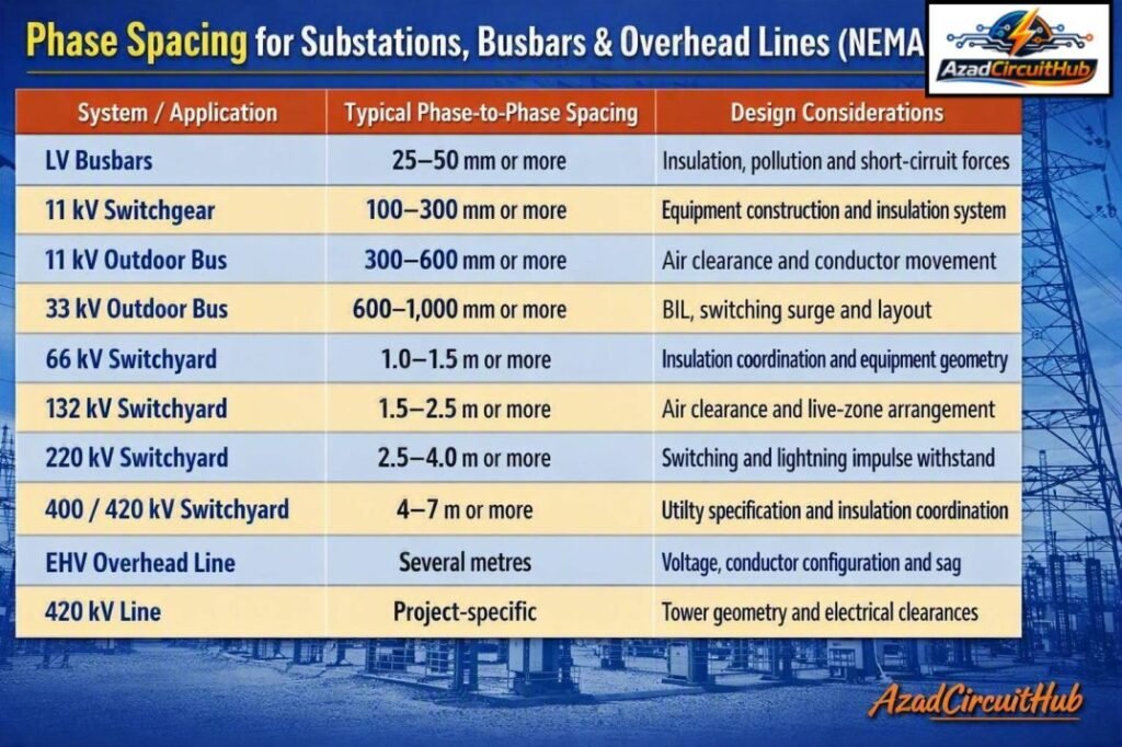
Table of Contents
Table of Contents
Quick Phase Spacing for Substations, Busbars & Overhead Lines
The following values are useful preliminary design ranges. Final dimensions should always be verified against the applicable equipment standard, insulation coordination study, utility specification, and manufacturer drawings.
| System / Application | Typical Phase-to-Phase Spacing Range | Common Design Consideration |
|---|---|---|
| LV busbars | 25–50 mm or more | Insulation, pollution and short-circuit forces |
| 11 kV switchgear | 100–300 mm or more | Equipment construction and insulation system |
| 11 kV outdoor bus | 300–600 mm or more | Air clearance and conductor movement |
| 33 kV outdoor bus | 600–1,000 mm or more | BIL, switching surge and layout |
| 66 kV switchyard | 1.0–1.5 m or more | Insulation coordination and equipment geometry |
| 132 kV switchyard | 1.5–2.5 m or more | Air clearance and live-zone arrangement |
| 220 kV switchyard | 2.5–4.0 m or more | Switching and lightning impulse withstand |
| 400/420 kV switchyard | 4–7 m or more | Utility specification and insulation coordination |
| EHV overhead line | Several metres | Voltage, conductor configuration and sag |
| 420 kV line | Project-specific | Tower geometry and electrical clearances |
These are engineering reference ranges, not universal code values. Actual phase spacing must be established from the governing standard and project design.
What Is Phase Spacing?
Phase spacing is the physical distance between the centers or closest energized portions of two different phases in an electrical system. It is also commonly described as phase-to-phase distance.
In an outdoor substation, the measurement may be taken between conductors, bus tubes, disconnect switch terminals, or other energized components. In overhead lines, engineers normally consider the conductor centerline positions and the minimum distance that can occur under wind, temperature, and mechanical loading.
Correct phase spacing provides sufficient dielectric strength between phases while also allowing the equipment to withstand mechanical and thermal forces during faults.
The required distance increases as system voltage and insulation requirements increase.
Phase Spacing for Substations
Phase spacing for substations is determined through a combination of electrical insulation requirements and physical equipment layout.
Outdoor substations generally have larger spacing than indoor switchgear because air is used as the primary insulation medium. Engineers must consider power-frequency withstand voltage, lightning impulse withstand voltage, switching impulse withstand voltage, altitude, atmospheric pollution, conductor movement, and maintenance access.
For example, a 132 kV outdoor bus arrangement will normally require considerably more spacing than an 11 kV installation.
| Nominal System Voltage | Typical Outdoor Phase Spacing | Typical Application |
|---|---|---|
| 11 kV | 0.3–0.6 m | Distribution substation |
| 33 kV | 0.6–1.0 m | Distribution / transmission |
| 66 kV | 1.0–1.5 m | Transmission switchyard |
| 132 kV | 1.5–2.5 m | HV substation |
| 220 kV | 2.5–4.0 m | EHV switchyard |
| 400/420 kV | 4–7 m or more | EHV transmission |
The actual value can differ substantially between utilities because equipment dimensions, insulation coordination, and national practices are not identical.
For indoor metal-enclosed equipment, the required distance can be much smaller because solid insulation, barriers, controlled clearances, and enclosure construction provide additional protection.
NEMA Recommended Phase Spacing
The term NEMA recommended phase spacing is often used by engineers searching for practical busbar and electrical equipment dimensions. However, NEMA standards should not be treated as one universal table of phase-to-phase distances for every voltage level.
NEMA standards cover specific types of electrical equipment and construction practices. IEEE standards and guides also address insulation coordination, substations, overhead lines, clearances, and electrical safety.
Therefore, the designer should identify the equipment category and applicable standard before selecting a spacing.
For an outdoor substation, the design process normally considers:
- Nominal system voltage.
- Maximum system voltage.
- Basic insulation level (BIL).
- Switching impulse requirements.
- Lightning impulse withstand.
- Altitude correction.
- Pollution and environmental conditions.
- Conductor movement.
- Short-circuit mechanical forces.
- Maintenance and safety clearances.
This approach is safer than selecting a spacing from a generic voltage chart.
EHV Bus Phase Spacing
EHV bus phase spacing becomes especially important at 220 kV, 400 kV and 420 kV substations. At these voltage levels, a small change in conductor position can significantly affect electrical clearance.
An EHV bus phase spacing arrangement must account for both normal and abnormal conditions. Wind, temperature rise, short-circuit forces, seismic movement, and conductor sag can change the effective distance between energized phases.
Typical preliminary values are shown below.
| Voltage Class | Approximate Preliminary Phase Spacing |
|---|---|
| 132 kV | 1.5–2.5 m |
| 220 kV | 2.5–4.0 m |
| 275 kV | 3–4.5 m |
| 400 kV | 4–6 m |
| 420 kV | 4–7 m or more |
A commonly discussed design figure is 7 meters for 420 kV phase spacing. However, 420kV phase spacing 7 meter should not be interpreted as a mandatory universal requirement. Some switchyards use smaller or larger dimensions depending on the equipment arrangement, insulation coordination, conductor geometry, and utility standard.
Centerline Phase to Phase Spacing
Centerline phase to phase spacing refers to the distance measured from the centerline of one conductor or bus phase to the centerline of the adjacent phase.
This measurement is useful when developing substation general arrangements, bus support structures, and overhead line tower geometry.
For a round conductor or tubular bus, the centerline dimension is different from the actual air gap between conductor surfaces.
For example, if two tubular bus conductors have an outside diameter of 100 mm and their centerlines are 1,000 mm apart:
| Parameter | Value |
|---|---|
| Phase centerline distance | 1,000 mm |
| Conductor diameter | 100 mm |
| Approximate surface-to-surface distance | 900 mm |
The distinction is important because insulation coordination and electrical clearance checks generally depend on the minimum physical air distance, not simply the centerline dimension.
Phase Spacing for Disconnect Switch
Phase spacing for disconnect switch arrangements depends on the switch design, voltage class, terminal configuration, operating mechanism, and manufacturer-approved clearances.
A disconnect switch must maintain adequate insulation between phases during both normal operation and switching conditions. The arrangement must also account for the movement of the switch blade.
| Disconnect Application | Main Design Factors |
|---|---|
| Indoor MV switchgear | Insulation, barriers and enclosure |
| Outdoor 11 kV | Air clearance and blade movement |
| 33 kV disconnect | BIL and mechanical movement |
| 132 kV disconnect | Phase clearance and operating geometry |
| 220 kV disconnect | Switching impulse and live-zone clearance |
| 400/420 kV disconnect | EHV insulation coordination and structure geometry |
The manufacturer’s certified dimensional drawing should be used for final disconnect switch installation. A generic spacing chart should only be used during preliminary layout work.
For equipment assemblies, engineers should also distinguish between phase-to-phase clearance, phase-to-earth clearance, and clearance across an open disconnect gap.
Phase Spacing in Busbars
Busbar spacing depends strongly on whether the bus is bare, insulated, enclosed, or installed inside switchgear.
For bare copper or aluminium busbars, spacing must provide sufficient dielectric clearance while allowing for thermal expansion and electrodynamic forces during a short circuit.
Short-circuit current can create significant forces between parallel busbars. Therefore, increasing phase spacing alone does not replace proper support design.
Important busbar design parameters include:
- Rated voltage
- Rated current
- Short-time withstand current
- Peak withstand current
- Busbar material
- Busbar dimensions
- Support spacing
- Insulation type
- Ambient temperature
- Altitude
- Pollution level
For LV and MV assemblies, designers should also verify the applicable IEC or NEMA equipment requirements rather than applying outdoor substation dimensions.
When checking equipment assemblies, you can also use our guide on phase to phase clearance as per iec 61439 to compare the clearance requirements for low-voltage assemblies with the much larger air clearances used in outdoor HV substations.
Phase Spacing on 11 kV Overhead Lines
The span in 11kv line is related to the distance between supports, while phase spacing refers to the separation between the individual phase conductors. These are different design parameters.
An 11 kV overhead line can use horizontal, vertical, or triangular conductor arrangements. The selected arrangement affects tower width, phase clearance, wind loading, and conductor swing.
| 11 kV Line Parameter | Typical Engineering Consideration |
|---|---|
| Phase arrangement | Horizontal, vertical or triangular |
| Phase spacing | Project and utility dependent |
| Span length | Depends on terrain and conductor |
| Conductor sag | Temperature dependent |
| Wind swing | Must be considered |
| Pole/tower strength | Based on mechanical loading |
| Ground clearance | Applicable electrical standard |
The phrase span in 11kv line should therefore not be confused with phase spacing. A longer span can increase conductor sag and swing, which may reduce the minimum phase-to-phase distance under certain weather conditions.
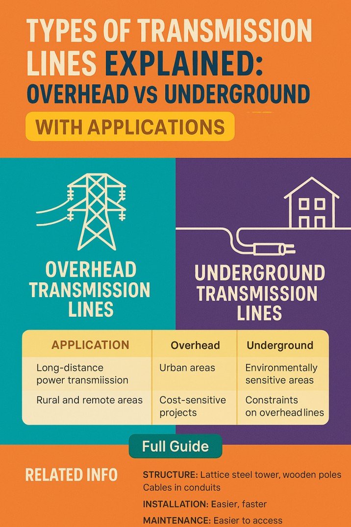
Phase Spacing for Overhead Transmission Lines
Overhead transmission line phase spacing is influenced by voltage, conductor type, tower geometry, sag, wind, and electrical performance.
At higher voltages, increasing the distance between phases helps reduce the probability of air breakdown. However, tower dimensions and right-of-way requirements also increase.
Engineers should check the closest approach of conductors under maximum sag and maximum wind swing rather than relying only on the nominal tower drawing.
For bundled conductors, the phase arrangement also affects corona performance, audible noise, radio interference, and electric field distribution.
Phase to Phase Clearance vs Phase Spacing
Although the terms are sometimes used interchangeably, they can describe different dimensions.
Phase spacing commonly refers to the designed physical separation between phases. Phase-to-phase clearance normally means the minimum air distance between energized parts.
For example:
| Measurement | Meaning |
|---|---|
| Centerline spacing | Center of one conductor to center of another |
| Phase spacing | General physical separation between phases |
| Phase-to-phase clearance | Minimum distance between energized surfaces |
| Phase-to-earth clearance | Minimum distance from live part to grounded object |
| Creepage distance | Distance along an insulating surface |
Understanding these differences helps prevent mistakes when converting equipment drawings into substation layout dimensions.
For a quick preliminary check of electrical clearances, a Phase to Phase Clearance Calculator can help estimate the required separation before the final insulation coordination and equipment review.
Factors That Change Required Phase Spacing
There is no single phase spacing value that works for every substation or transmission line. Several conditions can require a larger distance.
System Voltage
Higher voltage generally requires greater air insulation distance. The maximum operating voltage should be considered rather than relying only on the nominal voltage.
Altitude
Air density decreases at higher elevations. This can reduce dielectric strength and may require correction of clearances.
Pollution
Salt, dust, industrial contamination, and moisture can increase insulation stress. Outdoor installations in heavily polluted areas may require additional insulation measures.
Switching and Lightning Surges
Impulse voltages can be much higher than normal operating voltage. Insulation coordination must therefore consider transient overvoltages.
Wind and Conductor Movement
Overhead conductors and flexible bus connections can move under wind. The minimum clearance should be checked during the most unfavorable position.
Short-Circuit Forces
High fault current creates electromagnetic forces between bus conductors. Mechanical movement must not reduce the required electrical clearance.
How to Calculate Preliminary Phase Spacing
A practical preliminary design can follow these steps:
- Identify the nominal and maximum system voltage.
- Determine the applicable insulation level and withstand requirements.
- Identify the governing NEMA, IEEE, IEC, utility, or national standard.
- Apply altitude and environmental corrections.
- Determine phase-to-earth and phase-to-phase clearances.
- Add allowances for conductor movement and mechanical tolerances.
- Check equipment manufacturer dimensions.
- Verify the final arrangement through insulation coordination.
For a new substation, the final dimension should come from the coordinated electrical and mechanical design rather than from a generic internet chart.
Common Phase Spacing Design Mistakes
Several errors occur repeatedly during preliminary substation and overhead line design.
| Mistake | Why It Matters |
|---|---|
| Using nominal voltage only | Maximum voltage may be higher |
| Ignoring altitude | Air insulation strength changes |
| Confusing centerline and air gap | Actual clearance may be smaller |
| Ignoring conductor swing | Minimum clearance can be reduced |
| Copying another substation layout | Standards and equipment may differ |
| Ignoring disconnect blade movement | Operating clearance can become inadequate |
| Using only phase-to-phase clearance | Phase-to-earth clearance is also critical |
| Ignoring short-circuit forces | Bus movement can reduce clearance |
A good design therefore considers electrical, mechanical, environmental, and maintenance requirements together.
For equipment layouts where IEC 61439 applies, compare the assembly-specific requirements with outdoor HV practices using our detailed guide to phase to phase clearance as per iec 61439.
Frequently Asked Questions
What is the standard phase spacing for a substation?
There is no single standard phase spacing for every substation. The required distance depends on voltage, insulation level, altitude, environmental conditions, equipment type, conductor movement, and the applicable IEEE, NEMA, IEC, or utility requirements.
What is the typical phase spacing for 11 kV lines?
Typical 11 kV overhead line phase spacing can range from a few hundred millimetres depending on the conductor arrangement and utility practice. The final value must account for conductor swing, sag, insulation, and the governing distribution standard.
Is 7 meters the required phase spacing for 420 kV?
No. Seven metres can be used as a preliminary reference for some 420 kV switchyard arrangements, but it is not a universal mandatory value. Actual spacing depends on insulation coordination, equipment geometry, utility specifications, and site conditions.
What is the difference between phase spacing and phase-to-phase clearance?
Phase spacing generally describes the physical separation between phases, while phase-to-phase clearance usually refers to the minimum air distance between energized surfaces. Centerline spacing can be larger than the actual air gap because conductor diameter must be considered.
How is phase spacing selected for a disconnect switch?
Phase spacing for disconnect switches is selected according to voltage, insulation requirements, switch geometry, blade movement, terminal arrangement, and the manufacturer’s certified design. The manufacturer’s dimensional drawing should be used for final installation.
Final Design Checklist
Before approving a substation or overhead line layout, verify:
- Maximum system voltage
- BIL and impulse withstand requirements
- Phase-to-phase air clearance
- Phase-to-earth clearance
- Altitude correction
- Pollution level
- Conductor sag
- Wind swing
- Short-circuit forces
- Disconnect switch movement
- Busbar support arrangement
- Manufacturer clearances
- Applicable NEMA and IEEE requirements
- Utility-specific design standards
- National electrical safety requirements
Correct phase spacing is not simply a matter of selecting a distance from a voltage table. It is part of the wider insulation coordination and equipment layout process. For preliminary engineering, reference values can help establish the arrangement, but the final design should always be verified against the applicable standard, manufacturer data, and project-specific electrical studies.
Get new guides in your feed. Follow Electrical Insights on LinkedIn for new electrical standards guides, calculators and design tips from Azad Circuit Hub.
#PhaseSpacing, #SubstationDesign, #BusbarSpacing, #OverheadLines, #NEMA, #IEEE, #ElectricalClearance, #PowerSystems, #HighVoltage, #ElectricalEngineering