NEC Code for Variable Frequency Drives: Article 430 Part X Explained (2026)
The NEC code for variable frequency drives sits in Article 430, Part X, titled Adjustable-Speed Drive Systems. It tells you how to size the conductors that feed a drive, how to protect the drive and motor, where the disconnect goes and how to handle a bypass. If you install, inspect or design VFD circuits in the United States, this guide gives you the section numbers and the arithmetic in one place.
The rules are short, but they change the numbers you are used to. A drive is sized from its own input current, not only from the motor tables. Below you will find the Part X map, a worked 10 HP example, the 2026 changes, and short answers to the VFD questions people search in the USA: what a VFD is, its HS code, the three types and how to set one.
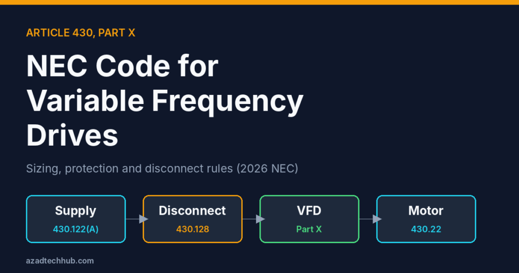
Quick answer: The NEC code for variable frequency drives is Article 430, Part X (430.120 to 430.132). Size the supply conductors at 125% of the drive’s rated input current (430.122(A)), the disconnect at 115% of that input current (430.128), and protect the circuit under 430.130 using the limits marked on the drive.
What Is the NEC Code for Variable Frequency Drives?
Article 430 covers motors, motor circuits and controllers. Part X adds the rules for adjustable-speed drives, and 430.120 says Parts I through IX still apply unless Part X modifies them. In other words, the NEC code for variable frequency drives is an add-on to the normal motor rules, not a replacement. For the full article, read our NEC article for motors guide.
Is a VFD a variable frequency drive? Yes. VFD stands for variable frequency drive, the electronic controller that changes the frequency and voltage supplied to an AC motor to control its speed. Other names are adjustable frequency drive (AFD), adjustable-speed drive (ASD), variable speed drive and inverter. The NEC calls the drive “power conversion equipment” and the whole assembly an “adjustable-speed drive system.” New to drives? Start with What is a Variable Frequency Drive? and the VFD working principle.
NEC Code for Variable Frequency Drives: Part X at a Glance
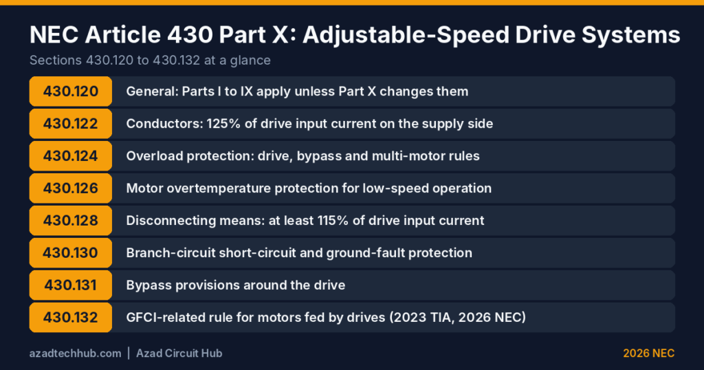
Here is the NEC code for variable frequency drives section by section:
| Section | What it covers | Rule of thumb |
|---|---|---|
| 430.120 | General | Parts I to IX apply unless Part X changes them |
| 430.122 | Conductors | Supply side at 125% of drive input current |
| 430.124 | Overload protection | Drive may provide it; bypass and multi-motor circuits need their own |
| 430.126 | Motor overtemperature | Protects the motor at low speed |
| 430.128 | Disconnecting means | At least 115% of drive input current |
| 430.130 | Branch-circuit short-circuit and ground-fault protection | Follow the drive marking |
| 430.131 | Bypass provisions | Separate protection for the bypass path |
| 430.132 | GFCI-related rule | Added by a 2023 TIA, carried into the 2026 NEC |
For where Article 430 sits among the nine chapters, open our NEC articles list.
Sizing Conductors Under the NEC Code for Variable Frequency Drives
Section 430.122(A) requires the branch-circuit or feeder conductors that supply the drive to have an ampacity of at least 125% of the drive’s rated input current. This is the biggest shift from a plain motor circuit, where 430.22 uses 125% of the table full-load current. Read the drive nameplate, not the motor.
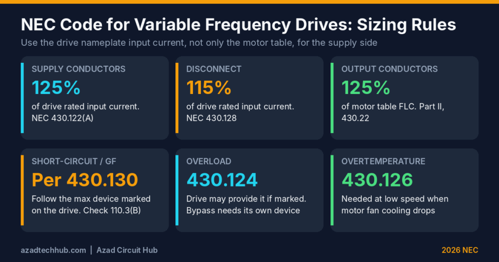
The conductors between the drive and the motor are different. They are sized on the motor using the normal Part II rules in 430.22, and the code warns that output and input ampacities are often not the same. Then check Table 310.16 and the 110.14(C) terminal temperature limits. Our motor cable size calculator and wire sizing for motors guide run those numbers, and the 3-phase cable size calculator checks voltage drop on long runs.
If one circuit feeds several motors, or a motor and other loads, 430.122 has its own rule for adding the remaining loads, so read the full section before you size the feeder. To pick the drive itself, use the VFD selection calculator and the VFD rating calculation guide, or follow how to size a VFD for a motor.
VFD Overload, Overtemperature and Short-Circuit Protection
Protection is where the NEC code for variable frequency drives has the most traps. Four sections matter:
- Overload (430.124): The drive can provide motor overload protection when it is listed and marked for it. A bypass circuit needs its own overload device, and each motor on a multi-motor drive needs individual overload protection.
- Overtemperature (430.126): A self-cooled motor loses fan airflow at low speed, so Part X requires overtemperature protection. Common solutions are a thermistor wired to the drive, a thermal protector in the motor, or a drive with a listed thermal function.
- Short-circuit and ground-fault (430.130): Follow the maximum fuse or breaker size and type marked on the drive or in its instructions, as 110.3(B) requires. Using a bigger device than the drive allows voids the listing.
- Bypass (430.131): The bypass path needs its own protection because the drive no longer sits in series with the motor.
Our overload relay setting calculator, motor overload setting table and guide to overcurrent setting in VFD for motors show the arithmetic. The wider rules sit in our NEC article for overcurrent protection.
VFD Disconnect Requirements Under the NEC Code for Variable Frequency Drives
The disconnect for an adjustable-speed drive system must be rated at least 115% of the drive’s rated input current (430.128), and it can sit in the incoming line to the drive. The usual motor rules still apply, including a disconnect in sight of the controller and, in most cases, one in sight of the motor (430.102).
Keep the working space clear in front of the drive and disconnect. See NEC article 110.26 A, clearance in front of panels and AC disconnect height.
Worked Example: 10 HP, 460 V Motor on a VFD
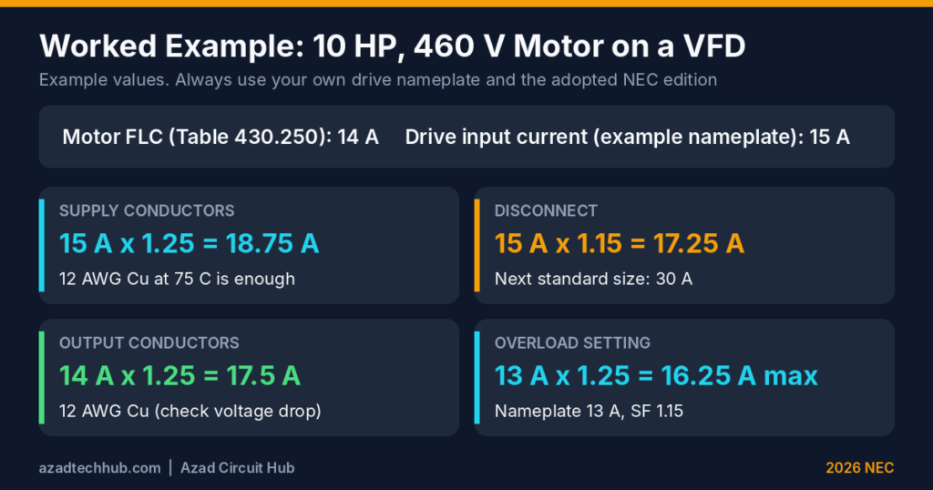
Here is the NEC code for variable frequency drives applied to a real circuit. Take a 10 HP, 460 V, three-phase motor. Table 430.250 gives 14 A, and the motor nameplate says 13 A with a 1.15 service factor. Assume the drive nameplate shows 15 A input. These are example values, so always use your own nameplates.
- Supply conductors: 15 A x 1.25 = 18.75 A. 12 AWG copper at 75 C is enough on ampacity.
- Disconnect: 15 A x 1.15 = 17.25 A, so a 30 A switch is the next standard size.
- Output conductors: 14 A x 1.25 = 17.5 A. 12 AWG copper works, then check voltage drop.
- Overload setting: 13 A x 1.25 = 16.25 A maximum.
- Branch-circuit device: use the maximum marked on the drive.
Three conductors plus a ground in conduit? Check the fill with our conduit fill calculator.
Grounding, Cable and Installation Rules for VFDs
Good installation matters as much as the numbers in the NEC code for variable frequency drives. Keep these points in mind:
- Follow the instructions. Section 110.3(B) makes the drive’s installation instructions part of the code, including cable length limits and filters.
- Ground it properly. The equipment grounding conductor follows Article 250. See our NEC article for grounding and bonding and grounding vs bonding guides.
- Control noise and heat. Drives create high-frequency noise and heat. Read our guides on the harmonic filter and heat dissipation.
- Test safely. Disconnect the motor leads from the drive before an insulation test, and use a meter with a low-pass filter when reading drive output. See our best clamp meter for electricians picks and insulation resistance tester guide.
2026 Changes to the NEC Code for Variable Frequency Drives
The 2023 NEC added 430.132 through a tentative interim amendment (TIA) on GFCI protection for motors fed by power conversion equipment, and Code Panel 17 carried the change into the 2026 edition, as Electrical Contractor magazine reports. Pool pump drives also fall under Article 680. The 2026 edition also adds Design BE and CE motors across Article 430, covered in our NEC article for motors guide. Confirm the edition your state enforces before you cite a section number.
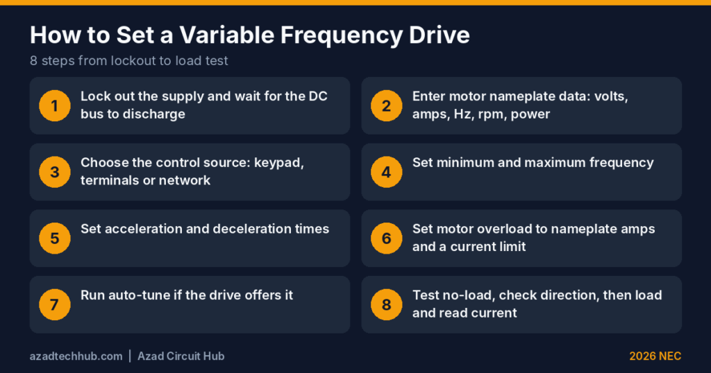
How to Set a Variable Frequency Drive
Menus differ by brand, but the order is the same. Setting the drive correctly also supports the NEC code for variable frequency drives, because the overload and current limits live in the drive menu. Always follow the drive manual:
- Lock out the supply and wait for the DC bus to discharge.
- Enter the motor nameplate data: voltage, amps, frequency, rpm and power.
- Choose the control source: keypad, terminals or network.
- Set minimum and maximum frequency. Avoid long low-speed runs on a self-cooled motor.
- Set acceleration and deceleration times. Ramps that are too short cause overcurrent or overvoltage trips. A braking resistor can help with fast stops.
- Set the motor overload to nameplate amps, plus a current limit.
- Run auto-tune if the drive offers it.
- Test with no load, check rotation, then load the motor and read the current.
If the drive trips, use our VFD troubleshooting tips.
What Are the Three Types of VFD?
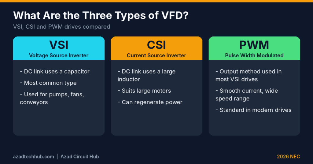
Most sources group drives into three types:
- Voltage source inverter (VSI): a capacitor DC link. It is the most common type and suits pumps, fans and conveyors.
- Current source inverter (CSI): a large inductor DC link. It suits large motors and can regenerate power.
- Pulse width modulated (PWM): the output method used in nearly all modern VSI drives, which is why many lists count it as a type.
Read our full guide to the types of VFD and the comparison of variable torque vs constant torque VFD.
What Is the HS Code for Variable Frequency Drives (VFDs)?
VFDs fall under HS heading 8504.40, static converters. In the US tariff schedule, the line commonly used is 8504.40.40, speed drive controllers for electric motors. Duties and extra tariffs change with country of origin, so confirm the 10-digit code and current rate with a licensed customs broker before you import.
NEC Code for Variable Frequency Drives FAQs
What NEC article covers VFDs?
Article 430, Part X, Adjustable-Speed Drive Systems (430.120 to 430.132).
What size wire do I need for a VFD?
The supply conductors need at least 125% of the drive’s rated input current. The motor leads follow the motor rules in 430.22.
Does a VFD need a disconnect?
Yes. It must be rated at least 115% of the drive’s input current (430.128).
Is there a free NEC PDF?
NFPA copyrights the code, but it offers free read-only access to NFPA 70 at nfpa.org after you register.
More Guides on the NEC Code for Variable Frequency Drives
- VFD guides hub and electrical calculators
- IEC standards for variable frequency drives
- Variable frequency drive for 3 phase motor and single phase frequency drive guide
- VFD in pumps and benefits of VFD in HVAC systems
- NEC article for branch circuits, NEC article 210.20 A and NEC article for generators
NEC Code for Variable Frequency Drives: Key Takeaways
The NEC code for variable frequency drives is Article 430, Part X. Remember the numbers: 125% of drive input current for supply conductors, 115% for the disconnect, and the drive’s marked limit for short-circuit protection. Bookmark this NEC code for variable frequency drives guide, confirm your local edition, and use our calculators to check the arithmetic.
Get new guides in your feed. Follow Electrical Insights on LinkedIn for new electrical standards guides, calculators and design tips from Azad Circuit Hub.