
NEC 392.22(B)(1)(c): Mixed Single Conductor Fill Formula
If a cable tray contains single conductors of different sizes, NEC 392.22(B)(1)(c) provides the method for determining the maximum allowable cable tray fill. Unlike installations where all conductors have the same diameter, mixed conductor installations require calculating the total cross-sectional area occupied by every cable. This approach prevents overcrowding, improves heat dissipation, and ensures the installation complies with the National Electrical Code (NEC).
Before performing any calculation, you can quickly estimate the allowable fill using our Cable Tray Fill Calculator according to NEC to verify compliance and reduce manual calculation errors.
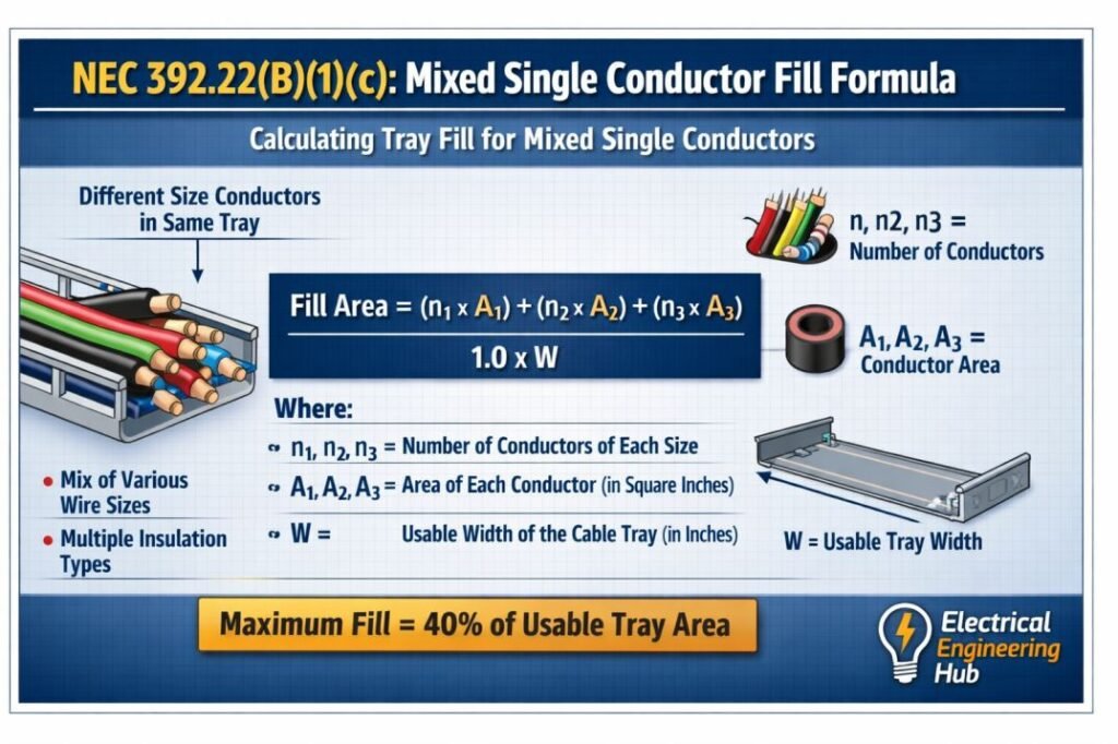
Table of Contents
Table of Contents
Quick Reference Chart
| Requirement | NEC 392.22(B)(1)(c) |
|---|---|
| Applies To | Mixed single conductor cables |
| Cable Type | 1/0 AWG and larger |
| Calculation Method | Sum of cable areas |
| Basis of Calculation | Cross-sectional area |
| Goal | Prevent tray overfill |
| Standard | NEC Article 392 |
Formula Snapshot
| Parameter | Formula |
|---|---|
| Total Cable Area | Area of Cable 1 + Cable 2 + Area of Cable 3 + … |
| Allowable Fill | Depends on tray width and NEC limits |
| Compliance Check | Total Cable Area ≤ Maximum Tray Fill Area |
What NEC 392.22(B)(1)(c) Covers
NEC 392.22(B)(1)(c) specifically addresses cable trays containing multiple single conductor cables with different outside diameters. Since each cable occupies a different amount of tray space, simply counting the number of conductors is not acceptable.
Instead, every cable contributes its own cross-sectional area to the total occupied tray area. The combined area must remain within the maximum fill area permitted for the selected cable tray.
This method is commonly used in:
- Industrial power distribution
- Medium-voltage installations
- Large motor feeders
- Utility substations
- Renewable energy plants
- Data center power systems
Why Mixed Cable Fill Uses Area Instead of Diameter
When cables have different diameters, spacing becomes irregular. Larger conductors occupy much more space than smaller ones.
For example:
| Cable | Outside Diameter |
|---|---|
| 500 kcmil | 1.35 in |
| 350 kcmil | 1.15 in |
| 4/0 AWG | 0.90 in |
| 2/0 AWG | 0.75 in |
Although the diameter difference appears small, the occupied area increases with the square of the diameter. Therefore, NEC requires area calculations rather than diameter comparisons.
NEC 392.22(B)(1)(c) Mixed Single Conductor Fill Formula
The calculation follows a straightforward process.
Step 1: Obtain Each Cable Outside Diameter
Use the manufacturer’s published cable data instead of conductor size alone. Different insulation types can significantly change the overall diameter.
Step 2: Calculate Individual Cable Area
For each conductor:
Cable Area = π × (Outside Diameter ÷ 2)²
Step 3: Multiply by Quantity
If multiple conductors have the same diameter:
Total Area = Individual Area × Number of Conductors
Step 4: Add Every Cable Area
The combined occupied area equals the sum of all cable areas.
Step 5: Compare With Allowable Tray Fill
The total occupied area must remain below the maximum area permitted for the selected cable tray under NEC requirements.
Instead of calculating each conductor manually, many engineers prefer using the Cable Tray Fill Calculator according to NEC to instantly verify tray compliance for mixed conductor installations.
Worked Example
Consider the following installation.
| Cable Size | Quantity | Outside Diameter (in) |
|---|---|---|
| 500 kcmil | 6 | 1.35 |
| 350 kcmil | 3 | 1.15 |
| 4/0 AWG | 4 | 0.90 |
Calculate Individual Areas
| Cable | Area (sq in) |
|---|---|
| 500 kcmil | 1.43 |
| 350 kcmil | 1.04 |
| 4/0 AWG | 0.64 |
Multiply by Quantity
| Cable | Quantity | Total Area (sq in) |
|---|---|---|
| 500 kcmil | 6 | 8.58 |
| 350 kcmil | 3 | 3.12 |
| 4/0 AWG | 4 | 2.56 |
Total Occupied Area
Total Fill Area
= 8.58 + 3.12 + 2.56
= 14.26 square inches
The calculated value is then compared with the allowable tray fill area specified for that tray width and cable tray type.
Common Installation Applications
NEC 392.22(B)(1)(c) is frequently applied in projects where multiple feeder sizes are routed together.
| Industry | Typical Mixed Conductors |
|---|---|
| Manufacturing | Motor feeders |
| Solar Plants | Inverter outputs |
| Oil & Gas | Process equipment feeders |
| Water Treatment | Pump motors |
| Utility Stations | Distribution feeders |
| Commercial Buildings | Main power feeders |
Mixed conductor installations are becoming more common because modern facilities often expand in phases. Additional feeders are installed without replacing existing cable trays.
Factors That Influence Tray Fill
Several variables affect the final cable tray fill calculation.
| Factor | Impact |
|---|---|
| Cable insulation | Changes outside diameter |
| Cable manufacturer | Different overall dimensions |
| Tray width | Determines allowable fill |
| Cable quantity | Directly increases occupied area |
| Future expansion | Requires spare tray capacity |
| Cable arrangement | Affects installation efficiency |
Engineers normally leave additional tray capacity for future circuits rather than designing at the absolute NEC limit.
Common Calculation Mistakes
The following mistakes frequently lead to non-compliant installations.
| Mistake | Result |
|---|---|
| Using conductor diameter instead of overall cable diameter | Incorrect fill calculation |
| Ignoring insulation thickness | Underestimation of tray fill |
| Mixing NEC rules for identical conductors | Incorrect method |
| Forgetting spare conductors | Tray overload |
| Using nominal dimensions | Inaccurate calculations |
Always verify cable dimensions using the manufacturer’s latest catalog.
Design Tips for Engineers
Following a few practical design practices improves both safety and maintainability.
- Verify actual cable outside diameters before design.
- Reserve spare tray capacity for future additions.
- Group similar cable sizes where practical.
- Keep power and control cables separated when required.
- Confirm cable tray width before ordering materials.
- Check installation drawings against NEC fill limits.
These practices reduce future modifications and simplify cable routing.
Relationship With Other NEC Cable Tray Fill Rules
Each subsection of NEC Article 392 applies to a different cable arrangement.
| NEC Section | Application |
|---|---|
| NEC 392.22(B)(1)(a) | Identical single conductors |
| NEC 392.22(B)(1)(b) | Alternate identical conductor arrangements |
| NEC 392.22(B)(1)(c) | Mixed single conductor cables |
| NEC 392.22(C) | Multiconductor cables |
Selecting the correct subsection is essential because each uses a different calculation method.
Best Practices for NEC Compliance
Successful cable tray design goes beyond meeting minimum code requirements. Engineers should also consider cable accessibility, heat dissipation, future expansion, and maintenance requirements. During project design, verify every cable diameter from manufacturer data sheets, calculate the total occupied area accurately, and compare it against the permitted tray fill before procurement. Performing these checks early helps avoid costly field modifications and keeps installations compliant with NEC 392.22(B)(1)(c).
For large industrial projects with dozens of different cable sizes, manual calculations can become time-consuming. Using the Cable Tray Fill Calculator according to NEC provides a faster way to validate mixed single conductor tray fill while reducing calculation errors.
Related Guides & Tools
- Cable Tray Fill Calculator (NEC 392)
- NEC 392.22(A)(1)(a) Explained
- NEC 392.22(A) Multiconductor Cable Tray Fill Rules
- NEC 392.22(B) Single Conductor Cable Tray Fill Rules
Frequently Asked Questions
Does NEC 392.22(B)(1)(c) apply to identical conductors?
No. It applies when the cable tray contains single conductors of different outside diameters. Identical conductors are covered under other subsections of NEC 392.22(B)(1).
Why is cable area used instead of cable diameter?
Cable area provides a true representation of the tray space occupied by each conductor. Diameter alone does not accurately account for the space required by cables of different sizes.
Can manufacturer dimensions differ?
Yes. Two cables with the same conductor size may have different outside diameters because of insulation thickness, jacket material, or construction. Always use the manufacturer’s published dimensions.
Is future tray capacity required by NEC?
The NEC does not require spare capacity, but many engineers intentionally leave additional tray space to simplify future expansion and reduce the need for new cable trays.
Conclusion
NEC 392.22(B)(1)(c) establishes the correct method for calculating cable tray fill when multiple single conductor cable sizes are installed together. Instead of relying on conductor count, the code requires summing the cross-sectional area of every cable and comparing that value with the allowable tray fill.
This method produces safer, more accurate cable tray designs while improving airflow and simplifying future maintenance. By using manufacturer dimensions and validating results with a reliable calculation tool, engineers can confidently design compliant mixed-conductor cable tray systems.
Follow Us on Social:
Subscribe our Newsletter on Electrical Insights for latest updates from Electrical Engineering Hub
#NEC39222B1C, #CableTray, #ElectricalEngineering, #NECCode, #ConductorFill, #CableTrayDesign, #ElectricalStandards, #PowerSystems, #IndustrialElectrical, #ElectricalInstallation
