
NEC 392.22(A)(1)(a) Explained: Mixture of Cables in Cable Trays
Understanding NEC 392.22 is essential for anyone designing, installing, or inspecting cable tray systems. One of the most misunderstood parts of Article 392 is the rule covering the mixture of cables in cable trays. Engineers often ask whether different cable types can occupy the same tray and what conditions must be met to remain code compliant.
This guide explains NEC 392.22(A)(1)(a) in simple language, provides practical examples, and highlights common installation mistakes.
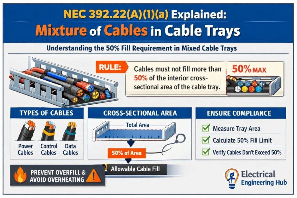
Table of Contents
Table of Contents
| Quick Reference | Details |
|---|---|
| NEC Article | NEC 392.22 |
| Topic | Mixture of Cables in Cable Trays |
| Applies To | Cable Tray Wiring Systems |
| Primary Requirement | Cable mixture depends on cable type and installation conditions |
| Common Users | Electrical Engineers, Contractors, Inspectors, Designers |
| Related Calculation | Cable Tray Fill Calculator |
Before checking cable combinations, use our Cable Tray Fill Calculator to verify tray capacity and ensure the installation remains within NEC fill requirements.
What is NEC 392.22?
NEC 392.22 contains the cable fill requirements for cable tray systems. It explains how much space different cable types can occupy and under which conditions they may be installed together.
The article applies to various cable trays including:
- Ladder cable tray
- Ventilated trough cable tray
- Solid bottom cable tray
- Channel cable tray
- Wire mesh cable tray where permitted
Rather than using a single fill rule, NEC 392.22 classifies requirements according to cable construction and voltage ratings.

Mixture of Cables in Cable Trays
The phrase Mixture of Cables in Cable Trays refers to installing different cable constructions inside the same cable tray.
Typical examples include:
| Cable Type | Common Application |
|---|---|
| Power Cables | Feeders and distribution |
| Control Cables | Industrial automation |
| Instrumentation Cables | Process control |
| Type TC Cable | Industrial facilities |
| MV Cables | Medium-voltage distribution |
| Fiber Optic Cables | Communication systems |
Although these cables may physically fit inside one tray, NEC 392.22 specifies when this arrangement is acceptable.
Mixing Cables in a Cable Tray: NEC 392.22(A)(1)(a)
NEC 392.22(A)(1)(a) addresses cable fill requirements where a mixture of single-conductor and multiconductor cables is installed in a cable tray.
In a standard cable tray system, multiple conductor cables are arranged based on their conductor size and insulation. The selection of cable tray width should be made using Table 392.22(A), specifically considering the calculations in Column 2 of that table.
The purpose of this rule is to maintain:
- Proper heat dissipation
- Adequate ventilation
- Safe cable support
- Long cable life
- Electrical safety
Instead of allowing installers to fill every available space, the code limits cable placement to ensure the tray continues to perform safely under operating conditions.
Cable Placement Based on Conductor Size
Cables with No. 4/0 AWG or Larger Conductors
Cables with conductors No. 4/0 AWG or larger cannot be stacked on top of each other. This restriction exists to prevent physical damage that might occur due to excessive weight and pressure. When calculating the total cable diameter for placement, it is necessary to sum the individual diameters of all cables in the tray.
For example, in an illustrated case, the total diameter added up to 12.6 inches. Since these cables contain multiple conductors inside a single jacket, proper spacing must be maintained to avoid insulation breakdown and overheating.
Cables with Smaller Than No. 4/0 AWG Conductors
On the other hand, cables with smaller than No. 4/0 AWG conductors are allowed to be stacked on top of each other. Unlike larger conductors, these cables pose a lower risk of damage from compression. Therefore, they can be placed in layers within the tray, optimizing space utilization.
Selecting the Right Cable Tray
The next step in ensuring NEC compliance is choosing the appropriate cable tray size and configuration. Based on the conductor sizes and their arrangement, the selection process must adhere to the NEC 392.22(A) table, considering spacing, mechanical protection, and heat dissipation.
Proper installation following 392.22(A)(1)(a) enhances system longevity, reduces safety hazards, and ensures the cable tray meets regulatory standards.
392.22(A)(1) Single-Conductor Cables.
Where single-conductor cables are 4/0 AWG or larger, the allowable fill area shall not exceed the values in Table 392.22(A).Where single-conductor cables smaller than 4/0 AWG are installed, the allowable fill shall not exceed 50 percent of the interior cross-sectional area of the cable tray.
Where a mixture of cables 4/0 and larger and smaller than 4/0 are installed in the same tray, the allowable fill shall not exceed the most restrictive fill area applicable.
Why the Code Allows Mixed Cable Installations
Industrial plants rarely use separate trays for every cable type.
A single tray often carries:
- Motor feeders
- PLC cables
- Instrument loops
- Communication cables
- Auxiliary power cables
Allowing a controlled mixture of cables reduces installation costs while maintaining safety.
However, installers must still consider:
| Design Factor | Importance |
|---|---|
| Cable diameter | Determines tray fill |
| Cable spacing | Improves cooling |
| Voltage rating | Prevents unsafe combinations |
| Cable insulation | Ensures compatibility |
| Heat generation | Reduces overheating risk |
Cable Tray Fill Still Matters
Many installers focus only on whether different cables may occupy the same tray. The actual tray fill is equally important.
Exceeding the allowable cable fill can result in:
- Excessive cable temperature
- Reduced ampacity
- Difficult maintenance
- Poor ventilation
- Code violations
Before finalizing any installation, calculate the tray capacity using the Cable Tray Fill Calculator to verify compliance with NEC cable fill requirements.
Practical Example of NEC 392.22
Consider a manufacturing facility installing:
| Cable | Quantity |
|---|---|
| 4/C Power Cable | 8 |
| Control Cable | 12 |
| Instrument Cable | 20 |
| Fiber Cable | 4 |
The engineer plans to place all cables inside one ladder tray.
To comply with NEC 392.22, the engineer should verify:
- Cable types permitted together
- Cable tray fill
- Tray width
- Cable support
- Temperature considerations
- Applicable ampacity adjustments
Only after these checks can the installation be considered compliant.
Common Applications
NEC 392.22 is frequently applied in:
| Industry | Typical Installation |
|---|---|
| Oil & Gas | Process equipment |
| Power Plants | Generator auxiliaries |
| Solar Power Plants | DC and AC cable trays |
| Water Treatment | Pump control systems |
| Manufacturing | Motor control centers |
| Commercial Buildings | Distribution feeders |
Each installation may contain multiple cable types within a common tray.
Common Mistakes When Installing Mixed Cables
Many field installations fail inspections because of avoidable mistakes.
Overfilling the Tray
Even if different cables are permitted together, exceeding allowable fill violates NEC requirements.
Ignoring Heat Build-Up
Large power cables generate heat. Bundling them tightly with smaller control cables reduces cooling.
Mixing Incompatible Cable Types
Not every cable construction is intended to share the same cable tray.
Always verify cable identification markings before installation.
Poor Cable Arrangement
Large cables should not crush smaller instrumentation cables.
Proper layering improves maintenance and extends cable life.
Skipping Fill Calculations
Visual estimation often results in incorrect tray sizing.
Using a proper fill calculation prevents costly redesigns.
Best Practices for Mixture of Cables in Cable Trays
Following industry best practices improves both safety and maintenance.
| Best Practice | Benefit |
|---|---|
| Verify NEC requirements | Code compliance |
| Separate high-heat circuits where practical | Better cooling |
| Maintain cable identification | Easier maintenance |
| Use tray covers only where appropriate | Environmental protection |
| Leave future expansion space | Easier upgrades |
| Support heavy cables correctly | Prevent cable damage |
These practices reduce installation issues and simplify future modifications.
Relationship Between NEC 392.22 and Cable Ampacity
Cable fill directly affects cable temperature.
As cable density increases:
- Heat dissipation decreases.
- Cable operating temperature rises.
- Ampacity may require adjustment.
- Cable insulation experiences greater thermal stress.
Proper tray design balances cable capacity with thermal performance.
Inspection Checklist
Before approving a cable tray installation, inspectors commonly verify the following items.
| Inspection Item | Status |
|---|---|
| Correct cable tray type | ✔ |
| Proper cable support | ✔ |
| Cable identification visible | ✔ |
| Fill requirements satisfied | ✔ |
| Mixed cable installation permitted | ✔ |
| Adequate working space | ✔ |
This checklist helps ensure long-term reliability and code compliance.
How Engineers Select the Correct Cable Tray
Engineers generally evaluate several factors before installing mixed cables.
These include:
- Cable quantity
- Largest cable diameter
- Future expansion
- Environmental conditions
- Mechanical strength
- Ventilation requirements
- Voltage classification
Selecting a slightly larger tray often simplifies future additions while improving airflow around existing cables.
For accurate sizing before purchasing materials, engineers should verify dimensions using the Cable Tray Fill Calculator, which helps determine whether the selected tray meets NEC fill limits for the planned cable installation.
Related Guides & Tools
- Cable Tray Fill Calculator (NEC 392)
- NEC 392.22(B) Single Conductor Cable Tray Fill Rules
- NEC 392.22(A) Multiconductor Cable Tray Fill Rules
Frequently Asked Questions
Does NEC 392.22 allow different cable types in one cable tray?
Yes. NEC 392.22 permits certain mixed cable installations when all applicable requirements for cable type, tray fill, support, and installation conditions are satisfied.
Why is cable tray fill important?
Proper cable fill maintains airflow, limits cable heating, supports safe ampacity, and ensures compliance with the National Electrical Code.
Does NEC 392.22 apply to industrial facilities?
Yes. The article is widely used in industrial plants, commercial buildings, power stations, renewable energy projects, and infrastructure installations that use cable tray systems.
Can power and control cables share the same tray?
They can in many installations, provided the cable types are permitted together and all NEC installation requirements are met.
Conclusion
When installing any mixture of cables in a cable tray, adherence to NEC 392.22(A)(1)(a) is essential. No. 4/0 AWG or larger conductors must be placed side by side without stacking, whereas smaller than No. 4/0 AWG conductors can be layered. Selecting the correct tray width from Table 392.22(A) ensures compliance, safety, and efficiency in electrical installations.
Note: According to NEC 392.22(A)(1), cable fill limits differ based on conductor size.
- For single-conductor cables 4/0 AWG and larger, refer to Table 392.22(A).
- For cables smaller than 4/0 AWG, the fill area must not exceed 50% of the tray’s cross-sectional area.
- When both types are installed together, the most restrictive fill area must be used.
Whether you are designing a new industrial facility or upgrading an existing installation, always verify cable compatibility, calculate tray capacity, and follow the applicable provisions of NEC 392.22. Careful planning today leads to safer, more reliable cable tray systems throughout the life of the installation.
Get new guides in your feed. Follow Electrical Insights on LinkedIn for new electrical standards guides, calculators and design tips from Azad Circuit Hub.
#NEC392 #CableManagement #ElectricalCables #NECCode #ElectricalSafety #CableInstallation #NECGuidelines #WiringStandards #ElectricalEngineering #ConduitWiring #CableMixing #NECCompliance #ElectricalCode #IndustrialWiring #CableRouting




Hello, the cable size reference is incorrect. The NEC has stipulations for 4/0 and larger, stipulations for cables less that 4/0 and also rules for having both in a single cable tray.
According to NEC 392.22(A)(1), cable fill limits differ based on conductor size.
For single-conductor cables 4/0 AWG and larger, refer to Table 392.22(A).
For cables smaller than 4/0 AWG, the fill area must not exceed 50% of the tray cross-sectional area.
When both types are installed together, the most restrictive fill area must be used.
I agree with your response. I whole heartedly agree that the NEC has rules to dictate the fill based on if the cable is larger than 4/0 or smaller than 4/0.
I don’t think I explained the issue correctly. This page, that I am currently on has a couple of errors. You use the cable size No. 4 AWG instead of using No. 4/0 AWG.
At the top of the page it states the following:
-Cables with No. 4 AWG or Larger Conductors (THIS SHOULD SAY “CABLES WITH No. 4/0 AWG or Larger Conductors)
-Cables with conductors No. 4 AWG or larger (THIS SHOULD SAY 4/0 LARGER) cannot be stacked on top of each other.
-Cables with Smaller Than No. 4 AWG Conductors (THIS SHOULD SAY “CABLES WITH No. 4/0 AWG or Smaller Conductors)
-On the other hand, cables with smaller than No. 4 AWG (THIS SHOULD SAY 4/0) conductors are allowed to be stacked on top of each other.
Thank you!
Thanks for the correction. Updated the post. Much Appreciated