Cable Tray Ampacity Derating: NEC 392.80 Explained
Designing a cable tray system involves more than selecting the correct tray width and cable size. One of the most critical considerations is Cable Tray Ampacity Derating, which determines how much current conductors can safely carry without exceeding their temperature rating.
Many engineers incorrectly assume that cable trays always require conductor derating. In reality, NEC 392.80 uses an installation-based approach rather than a fixed derating percentage. If conductors are installed under the conditions specified by the National Electrical Code (NEC), they are often permitted to carry 100% of their allowable ampacity from the applicable NEC ampacity tables. Additional reductions are required only when installation conditions increase conductor operating temperature.
This guide explains the actual requirements of nec 392.80 ampacity derating, when derating is required, and how to apply the code correctly in real-world electrical installations.
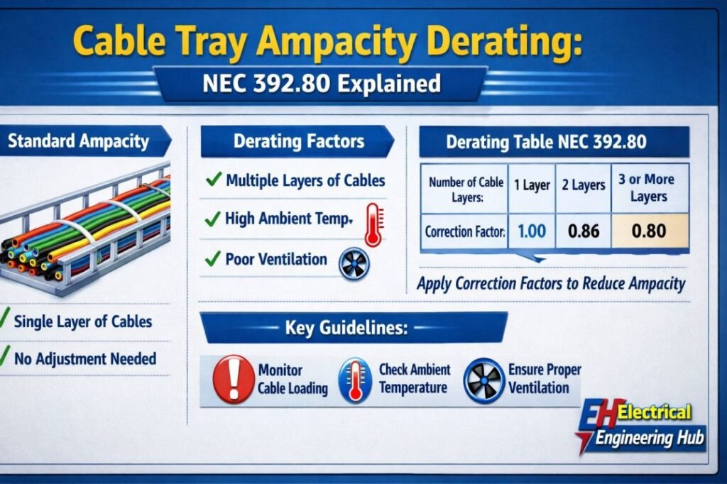
Table of Contents
Table of Contents
Cable Tray Ampacity Derating: NEC 392.80
| Item | NEC Requirement |
|---|---|
| Governing Code | NEC 392.80 |
| Purpose | Determine allowable conductor ampacity in cable trays |
| Fixed Derating Table | No |
| Based On | Installation method, cable type, conductor arrangement, ambient temperature |
| Temperature Corrections | NEC Table 310.15 correction factors |
| Typical Result | 100% ampacity may be permitted if installation complies with NEC 392.80 |
Before calculating conductor ampacity, verify that the tray satisfies allowable cable fill limits using our Cable Tray Fill Calculator according to NEC. An overloaded tray may comply electrically but still violate NEC fill requirements.
What is Cable Tray Ampacity Derating?
Cable Tray Ampacity Derating is the process of determining the allowable current-carrying capacity of conductors installed in a cable tray when installation conditions affect heat dissipation.
Every energized conductor produces heat according to the formula:
Heat Generated ∝ I²R
Where:
- I = Current
- R = Conductor Resistance
As current increases, conductor temperature rises rapidly. If adjacent cables prevent heat from escaping, insulation temperature can exceed its rating, reducing cable life and increasing the risk of failure.
Unlike conduit installations, cable trays are open to the surrounding air, allowing much better cooling. For this reason, the NEC does not automatically apply conductor adjustment factors simply because cables are installed in a tray.
Understanding NEC 392.80
NEC 392.80 covers the ampacity of insulated conductors installed in cable trays. Instead of assigning a universal derating percentage, the code evaluates several installation characteristics.
These include:
| Design Parameter | Effect on Ampacity |
|---|---|
| Cable Type | Determines applicable ampacity rules |
| Tray Construction | Affects heat dissipation |
| Single or Multiple Layers | Influences cable cooling |
| Ambient Temperature | May require correction factors |
| Conductor Spacing | Improves natural ventilation |
This means two cable trays carrying identical conductors can have different allowable ampacities depending on how the cables are installed.
Does NEC 392.80 Always Require Derating?
One of the biggest misconceptions is that all cable trays require ampacity derating.
The answer is No.
When conductors are installed under the conditions specified in NEC 392.80, full ampacity from the applicable NEC ampacity table is generally permitted.
The following table summarizes the requirements.
| Installation Condition | Ampacity Allowed |
|---|---|
| Single layer in ladder cable tray | 100% |
| Single layer in ventilated trough tray | 100% |
| Proper conductor spacing | 100% |
| Ambient above 30°C | Apply temperature correction factors |
| Multiple stacked cable layers | Engineering evaluation may be required |
| Poor ventilation | Additional analysis required |
Notice that the NEC does not provide a universal 80% or 70% derating factor for cable trays.
Cable Types Covered by NEC 392.80
Different insulated conductors are permitted in cable trays depending on their listing and installation method.
Common cable types include:
| Cable Type | Typical Application |
|---|---|
| Type TC | Industrial power distribution |
| Type MC | Commercial buildings |
| Medium Voltage Cable | Utility and industrial feeders |
| Single-Conductor Cable | Large power feeders |
| Instrumentation Cable | Process control systems |
| Control Cable | PLC and automation systems |
Each cable type follows its own installation requirements while remaining subject to NEC 392.80 ampacity provisions.
Cable Tray Ampacity Derating as per NEC 392.80
NEC allows different ampacity calculations depending on conductor installation.
Multiconductor Cables
For multiconductor cables installed in a ventilated cable tray in a single layer, ampacity is generally taken directly from the applicable NEC ampacity table.
This means:
- Select conductor size.
- Determine insulation temperature rating.
- Use the appropriate NEC ampacity table.
- Apply ambient temperature correction if required.
No additional cable tray derating is normally required.
Example:
| Parameter | Value |
|---|---|
| Cable | 4/C 500 kcmil Copper THHN |
| Installation | Ladder Tray |
| Ambient | 30°C |
| Allowable Ampacity | 100% of NEC Table Value |
Single-Conductor Cables
Single-conductor installations are treated differently because magnetic field effects and cable arrangement influence conductor temperature.
For single conductors installed:
- In one layer
- In a ventilated ladder tray
- With proper spacing
NEC 392.80 permits the use of full ampacity from the applicable NEC ampacity table.
This is why most high-current industrial feeders are installed in ladder cable trays rather than enclosed raceways.
Example – NEC 392.80 Ampacity Calculation
Consider the following installation.
| Parameter | Value |
|---|---|
| Cable | 500 kcmil Copper THHN |
| Tray Type | Ladder Cable Tray |
| Installation | Single Layer |
| Ambient Temperature | 30°C |
| Base NEC Ampacity | 430 A |
Since the installation satisfies NEC 392.80 requirements and the ambient temperature is the standard reference temperature, no correction factor is required.
Allowable ampacity = 430 A
If the same conductor were installed in a conduit with additional current-carrying conductors, different adjustment rules could apply.
This example demonstrates why cable trays often provide higher usable ampacity than enclosed raceways.
Ambient Temperature Correction Under NEC 392.80
One of the most overlooked aspects of Cable Tray Ampacity Derating is ambient temperature. While NEC 392.80 permits full ampacity under qualifying installation conditions, the ampacity values in NEC Table 310.16 are based on an ambient temperature of 30°C (86°F).
When the surrounding air temperature is higher, the conductor cannot dissipate heat as effectively, so its allowable ampacity must be reduced using the correction factors in NEC Table 310.15(B)(1).
90°C Insulation Correction Factors
| Ambient Temperature | Correction Factor |
|---|---|
| 30°C (86°F) | 1.00 |
| 35°C (95°F) | 0.96 |
| 40°C (104°F) | 0.91 |
| 45°C (113°F) | 0.87 |
| 50°C (122°F) | 0.82 |
| 55°C (131°F) | 0.76 |
| 60°C (140°F) | 0.71 |
These values apply after selecting the conductor ampacity from the appropriate NEC table.
Example of Ambient Temperature Derating
Consider a feeder installed in a ladder cable tray.
| Parameter | Value |
|---|---|
| Conductor | 500 kcmil Copper THHN |
| Base Ampacity | 430 A |
| Ambient Temperature | 40°C |
| Correction Factor | 0.91 |
Calculation:
Corrected Ampacity = 430 × 0.91 = 391 A
Although the cable tray itself does not require additional derating, the higher ambient temperature reduces the allowable current to 391 A.
Single Layer vs Multiple Layer Cable Installation
Cable arrangement has a direct impact on heat dissipation.
A single layer allows natural airflow around each cable, while stacked cables trap heat between adjacent conductors.
| Installation Method | Cooling Performance | Typical NEC Result |
|---|---|---|
| Single Layer | Excellent | Full ampacity permitted |
| Single Layer with Spacing | Best | Full ampacity permitted |
| Two Layers | Reduced | Engineering review recommended |
| Three or More Layers | Poor | Manufacturer or IEEE ampacity analysis may be required |
| Bundled Conductors | Poor | Additional thermal evaluation required |
For this reason, most industrial power distribution systems use a single layer whenever practical.
Recommended Conductor Spacing
Although NEC does not prescribe a universal spacing dimension for every installation, cable manufacturers commonly recommend maintaining approximately one cable diameter between adjacent single-conductor power cables to improve heat dissipation.
Benefits include:
- Lower conductor temperature
- Improved air circulation
- Higher usable ampacity
- Longer insulation life
- Easier future maintenance
Spacing becomes increasingly important as conductor size and load current increase.
Ladder Tray vs Ventilated Trough vs Solid-Bottom Tray
Cable tray construction significantly influences cooling performance.
| Tray Type | Airflow | Heat Dissipation | Typical Application |
|---|---|---|---|
| Ladder Tray | Excellent | Highest | Power distribution |
| Ventilated Trough | Very Good | High | Mixed power and control cables |
| Channel Tray | Moderate | Moderate | Small branch circuits |
| Solid-Bottom Tray | Limited | Lowest | Fiber optic and sensitive instrumentation |
Ladder cable trays remain the preferred choice for heavily loaded feeders because they maximize natural convection and simplify future cable additions.
Before selecting a tray width, verify cable occupancy using the Cable Tray Fill Calculator according to NEC. Confirming tray fill early in the design process helps avoid costly redesigns after conductor sizing is complete.
When Does Engineering Analysis Become Necessary?
Many engineers search for a fixed “cable tray derating percentage” for stacked or bundled conductors. However, NEC 392.80 does not provide one.
Engineering analysis is generally required when:
- Single-conductor cables are installed in multiple layers.
- Large conductors are tightly grouped with limited airflow.
- Ambient temperatures are unusually high.
- Large industrial feeders operate continuously near full load.
- The installation differs from the configurations recognized by NEC.
In these situations, designers often rely on:
- IEEE 835 – Standard Power Cable Ampacity Tables
- Neher-McGrath ampacity calculations
- Manufacturer ampacity data
- Project-specific thermal studies
These methods evaluate conductor temperature using actual installation conditions instead of applying an arbitrary derating percentage.
Common Design Mistakes
Many cable tray installations fail inspection because of preventable design errors.
| Mistake | Potential Consequence |
|---|---|
| Assuming all trays require 80% derating | Oversized conductors and unnecessary cost |
| Ignoring ambient temperature | Overheated conductors |
| Stacking large power cables | Reduced cooling and lower ampacity |
| Mixing heavily loaded feeders without planning | Localized heat buildup |
| Selecting tray width without checking fill | NEC non-compliance |
| Ignoring future expansion | Overfilled trays after modifications |
Most of these issues can be avoided during the design stage by reviewing both ampacity and tray fill together.
Best Practices for NEC-Compliant Cable Tray Design
Experienced EPC engineers typically follow these recommendations:
- Install power cables in a single layer whenever possible.
- Use ladder cable trays for high-current feeders.
- Separate heavily loaded circuits from low-power control cables.
- Allow adequate spacing between large single-conductor cables.
- Consider maximum summer ambient temperature during design.
- Leave spare tray capacity for future expansion.
- Verify both conductor ampacity and tray fill before issuing construction drawings.
Combining these practices improves safety, reduces operating temperature, and simplifies maintenance throughout the system’s service life.
For a complete cable tray design, use the Cable Tray Fill Calculator according to NEC before finalizing conductor sizing. Evaluating tray fill and ampacity together ensures compliance with both NEC Chapter 3 wiring methods and NEC 392.80 requirements.
Related Guides & Tools
- Cable Tray Fill Calculator (NEC 392)
- NEC 392.22(A)(1)(a) Explained
- NEC 392.22(A) Multiconductor Cable
- NEC 392.22(B) Single Conductor Cable
- NEC 392.22(B)(1)(c) Mixed Single Conductor
Frequently Asked Questions
Does NEC 392.80 include a cable tray derating table?
No. NEC 392.80 does not provide a universal derating table such as 70% or 80%. Instead, allowable ampacity depends on cable type, installation method, conductor arrangement, and ambient temperature.
Does a ladder cable tray require ampacity derating?
Not necessarily. When conductors are installed in a single layer under the conditions recognized by NEC 392.80, full ampacity from the applicable NEC ampacity table is generally permitted. Ambient temperature corrections must still be applied where required.
Why are cable trays often preferred over conduits for large feeders?
Cable trays provide better airflow, allowing conductors to dissipate heat more effectively. This often results in higher usable ampacity and easier future expansion compared with enclosed raceways.
Can tightly bundled cables use the same ampacity as spaced cables?
No. Bundled or stacked conductors have reduced cooling. In these cases, an engineering evaluation or manufacturer guidance may be necessary because NEC 392.80 does not assign a fixed derating percentage.
Conclusion
Cable Tray Ampacity Derating is not based on a universal reduction factor. The actual requirements of NEC 392.80 are installation-specific and depend on conductor type, tray construction, cable arrangement, and operating conditions. When conductors are installed in a single layer within a ventilated cable tray and the installation meets NEC requirements, they are generally permitted to use the full ampacity from the applicable NEC ampacity tables.
Ambient temperature corrections from NEC Table 310.15(B)(1) must still be applied whenever the surrounding temperature exceeds the standard reference condition.
Understanding this distinction helps engineers avoid both unsafe installations and unnecessarily oversized conductors. By evaluating tray fill, cable spacing, ambient temperature, and conductor ampacity together, designers can develop electrical systems that are safe, cost-effective, and fully compliant with NEC 392.80.
Get new guides in your feed. Follow Electrical Insights on LinkedIn for new electrical standards guides, calculators and design tips from Azad Circuit Hub.
CableTrayAmpacityDerating, #NEC39280, #CableTrayDesign, #AmpacityCalculation, #ElectricalEngineering, #CableSizing, #NECCode, #PowerDistribution, #ElectricalSafety, #IndustrialElectrical