
Single Point Grounding vs Multi Point Grounding: Differences, Applications & Best Practices
Choosing the correct grounding method is important for electrical safety, signal quality, equipment protection, and reliable system operation. The two common approaches are single-point grounding and multi-point grounding. The right choice depends on the system frequency, equipment type, cable arrangement, fault-current path, and sensitivity to electrical noise.
The comparison of single point grounding vs multi point grounding is especially important in control panels, instrumentation systems, PLC installations, communication networks, substations, and industrial automation.
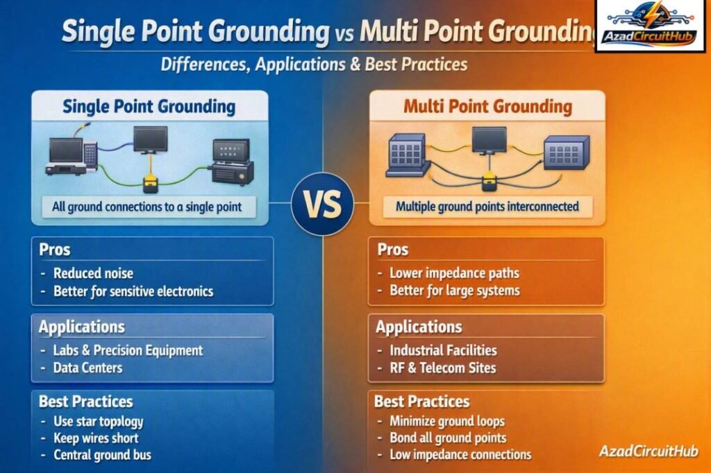
Table of Contents
Table of Contents
Single Point Grounding vs Multi Point Grounding: Quick Comparison
| Feature | Single Point Grounding | Multi Point Grounding |
|---|---|---|
| Ground connection | One primary grounding point | Several grounding points |
| Typical use | Low-frequency sensitive circuits | High-frequency systems and large installations |
| Ground loops | Easier to prevent | Greater risk if poorly designed |
| Noise control | Good at low frequencies | Often better at high frequencies |
| Cable arrangement | Simple | More complex |
| Ground potential differences | Can become significant over long distances | Usually lower across large structures |
| Common applications | Instrumentation, analog signals | RF, communication, high-frequency systems |
| Maintenance | Relatively simple | Requires more inspection |
| Main design concern | Ground voltage differences | Ground loops and circulating currents |
Understanding these differences helps engineers select a grounding architecture that matches the electrical and electromagnetic requirements of the installation.
What Is Single Point Grounding?
Single point grounding, sometimes called a star grounding arrangement, connects several grounding conductors to one defined reference point. Each circuit or equipment section has its own grounding conductor routed back to this common point.
The basic idea is to avoid unintended current paths between different grounding points. This can be particularly useful for sensitive analog signals and instrumentation circuits where small ground potential differences can affect measurements.
For example, a control system may have a dedicated instrument grounding bar connected to the designated grounding system at one point. Signal shields and reference conductors can then be arranged according to the equipment manufacturer’s requirements.
A simplified arrangement is:
| Equipment | Grounding Path |
|---|---|
| PLC panel | Dedicated conductor → common grounding point |
| Analog transmitter | Instrument ground → common grounding point |
| Control system | Ground bar → common grounding point |
| Signal reference | Controlled connection to designated ground |
| Panel enclosure | Protective earth according to system design |
The important point is that single-point grounding does not mean that only one physical earth electrode exists. It refers primarily to how grounding connections are arranged for a particular circuit or system.
What Is Multi Point Grounding?
Multi-point grounding uses several grounding connections distributed throughout an electrical installation. Equipment, structures, cable shields, panels, and other conductive parts may have multiple connections to the grounding network.
This arrangement can provide a low-impedance return path, particularly at higher frequencies. At high frequencies, conductor inductance becomes increasingly important. A long grounding conductor can have significant impedance even when its DC resistance is very low.
Multi-point grounding is therefore common in installations where electromagnetic compatibility, high-frequency noise, lightning protection, or RF performance is important.
A typical industrial grounding network may include:
- Main grounding grid
- Equipment grounding conductors
- Structural steel bonding
- Panel grounding bars
- Cable tray bonding
- Instrument grounding
- Shield termination points
- Surge protection grounding
The design must prevent unwanted circulating currents while maintaining effective bonding and fault-current paths.
Single Point Grounding vs Multi Point Grounding for Noise Control
Grounding and bonding have a major effect on electrical noise. However, neither method is automatically better for every application.
Single-point grounding can work well for low-frequency instrumentation because it limits the number of parallel ground paths. This reduces the possibility of circulating currents caused by small voltage differences between grounding points.
Multi-point grounding can perform better at high frequencies because short, distributed connections can reduce impedance. This is important for high-speed digital electronics, RF equipment, EMC control, and systems exposed to fast transient currents.
| Application | Preferred Approach | Main Reason |
|---|---|---|
| Low-frequency analog instrumentation | Often single point | Helps minimize ground-loop currents |
| PLC control system | Application dependent | Depends on manufacturer and system architecture |
| High-speed digital equipment | Often multi-point | Lower high-frequency impedance |
| RF equipment | Multi-point or engineered RF ground | High-frequency performance |
| Industrial power system | Distributed bonding | Fault-current and equipotential bonding |
| Sensitive measurement circuit | Often single point | Stable reference and reduced circulating current |
| Lightning protection | Distributed bonding/grid | Provides multiple low-impedance paths |
The correct solution should always consider the complete grounding and bonding system rather than selecting a method based only on the equipment name.
Main Difference Between Single Point and Multi Point Grounding
The fundamental difference is the number and location of intentional grounding connections.
In a single-point arrangement, circuit grounding paths are brought to one controlled reference point. In a multi-point arrangement, grounding connections are distributed across the installation.
The practical difference becomes more important as cable length and operating frequency increase.
For example, suppose two control panels are located far apart. A single long grounding conductor may have low resistance but relatively high inductive impedance during fast transients. Multiple short bonding connections may provide a better high-frequency path.
This is one reason why grounding design must consider both resistance and impedance.
Advantages and Disadvantages
| Grounding Method | Advantages | Disadvantages |
|---|---|---|
| Single point | Simple reference, reduced ground-loop risk, easy troubleshooting | Long conductors can have higher impedance at high frequency |
| Multi point | Low impedance at high frequency, effective bonding, distributed fault paths | More complex and can create circulating currents |
| Hybrid | Can combine low-frequency and high-frequency benefits | Requires careful engineering |
A hybrid approach is often used in modern industrial systems. For example, sensitive low-frequency signal references may use controlled single-point connections, while equipment enclosures and high-frequency bonding use short, distributed connections.
Single Point Grounding in Instrumentation Systems
Instrumentation systems often contain low-level signals such as 4–20 mA, thermocouple, RTD, load-cell, and analog voltage signals. These circuits can be affected by unwanted voltage differences and electromagnetic interference.
A carefully designed grounding system can reduce these problems.
For instrumentation, grounding should be coordinated with:
- Instrument cable shielding
- Analog and digital signal separation
- Cable tray arrangement
- Panel grounding
- Power supply grounding
- Signal reference conductors
- Surge protection
- Equipotential bonding
It is important to distinguish protective earth from signal reference and cable shield connections. They may have different functions even though they ultimately interact with the facility grounding system.
For a broader design guide, see our instrument earthing system resource to understand grounding arrangements, instrument earth bars, shield grounding, and practical installation methods.
Multi Point Grounding for High-Frequency Systems
High-frequency currents behave differently from DC or low-frequency currents. Skin effect, proximity effect, conductor inductance, and electromagnetic coupling become increasingly important.
A short, wide bonding connection can provide a much better high-frequency path than a long thin conductor.
This is why equipment cabinets, cable trays, doors, racks, and other metallic structures are often bonded with short connections where electromagnetic compatibility is important.
| Factor | Low Frequency | High Frequency |
|---|---|---|
| DC resistance | Very important | Less dominant |
| Inductance | Less dominant | Very important |
| Conductor length | Moderate concern | Major concern |
| Bonding geometry | Important | Very important |
| Ground loops | Major concern | Still important |
| Distributed bonding | Application dependent | Often beneficial |
For detailed practical guidance on instrument grounding and shield connections, our instrument earthing guide can help engineers compare grounding, bonding, shielding, and protective-earth requirements.
Ground Loops: The Main Concern
A ground loop occurs when two or more grounding paths form a conductive loop and a voltage difference exists between points in that loop. The resulting current can introduce noise into sensitive circuits.
Ground loops can cause:
- Analog measurement errors
- Hum in audio systems
- Communication problems
- Unstable sensor readings
- Unwanted circulating current
- Control-system interference
However, avoiding all multiple connections is not always the correct answer. Protective bonding and safety grounding must remain effective.
This is why the comparison of single point grounding vs multi point grounding should always be based on the purpose of each grounding connection.
Grounding Conductor Size and Installation
The grounding conductor must be selected according to the applicable electrical code, fault-current requirements, equipment characteristics, installation method, and local regulations.
For installations involving protective earth or equipment bonding, conductor sizing should not be based simply on the phase conductor size.
Important factors include:
- Prospective fault current
- Fault-clearing time
- Conductor material
- Installation method
- Thermal withstand
- Mechanical protection
- Applicable code
- Equipment manufacturer’s requirements
For a quick preliminary sizing check, use our earth cable size calculator before confirming the final conductor size against the applicable IEC, BS, NEC, or local requirements.
Which Grounding Method Should You Choose?
There is no universal answer to the question of single point grounding vs multi point grounding. The correct method depends on the electrical and physical characteristics of the system.
Single-point grounding is generally attractive for sensitive low-frequency circuits where preventing circulating ground currents is a priority.
Multi-point grounding is generally useful where low impedance, short bonding paths, high-frequency performance, or distributed equipotential bonding is required.
For large industrial facilities, a combination of methods is often more practical than using one method everywhere.
Practical Grounding Design Checklist
Before finalizing the grounding arrangement, check the following:
| Design Check | What to Verify |
|---|---|
| Grounding topology | Single, multi-point, or hybrid |
| Protective earth | Effective fault-current path |
| Instrument ground | Correct reference and isolation |
| Cable shields | Termination method and frequency |
| Ground loops | Unwanted parallel paths |
| Bonding | Panels, trays, structures and equipment |
| Conductor sizing | Code and fault-current requirements |
| High-frequency paths | Short and low-impedance connections |
| Surge protection | Proper grounding and bonding |
| Testing | Continuity, resistance and functional checks |
A grounding drawing should clearly identify protective earth, instrument earth, signal reference, shield connections, and bonding points. This makes commissioning and troubleshooting much easier.
Single Point Grounding vs Multi Point Grounding: Final Verdict
The best choice depends on what the grounding system needs to accomplish. Single-point grounding can provide a controlled reference and reduce circulating currents in sensitive low-frequency circuits. Multi-point grounding can provide effective low-impedance paths for high-frequency currents and equipotential bonding.
In many industrial installations, the most reliable solution is a properly engineered combination of both approaches. The grounding design should also follow the relevant electrical code, EMC requirements, equipment manufacturer’s instructions, and site-specific fault-current conditions.
The key is not simply choosing between single and multiple grounding points. Engineers should understand where current is expected to flow, what type of current is involved, and how grounding connections interact with the entire electrical system.
FAQs
Is single point grounding better than multi point grounding?
Neither method is universally better. Single-point grounding is often suitable for sensitive low-frequency instrumentation, while multi-point grounding can be more effective for high-frequency systems and distributed bonding.
What is the main disadvantage of multi point grounding?
The main concern is the possibility of unwanted circulating currents and ground loops when multiple grounding paths have voltage differences. Proper bonding and grounding design is needed to control these paths.
When should single point grounding be used?
Single-point grounding is commonly considered for sensitive low-frequency analog and instrumentation circuits where maintaining a controlled reference and minimizing circulating currents are important.
Why is multi point grounding used for high frequency?
At high frequencies, conductor inductance can make long grounding conductors ineffective. Multiple short bonding paths can provide lower impedance and improve high-frequency noise and EMC performance.
Are grounding and bonding the same thing?
No. Grounding generally establishes a connection to earth or a grounding reference, while bonding connects conductive parts together to maintain electrical continuity and reduce dangerous potential differences. They work together but have different functions.
Get new guides in your feed. Follow Electrical Insights on LinkedIn for new electrical standards guides, calculators and design tips from Azad Circuit Hub.
#SinglePointGrounding, #MultiPointGrounding, #ElectricalGrounding, #EarthingSystem, #GroundingDesign, #EMCGrounding, #ElectricalSafety, #GroundingBestPractices, #PowerSystems, #ElectricalEngineering
