
Motor Cable Sizing: Starting Current vs. Running Current
Motor cable sizing is not based on running current alone. An electric motor can draw several times its normal full-load current during startup, which affects voltage drop, conductor selection, breaker coordination, and motor performance. Choosing a cable only from the nameplate running current can lead to nuisance trips, excessive voltage drop, or overheating.
The correct approach considers the motor’s full-load current (FLC), starting current, cable length, installation method, ambient temperature, grouping, allowable voltage drop, and motor duty. This guide explains how starting and running current affect cable selection and how to choose a practical conductor size for common industrial and commercial motor circuits.
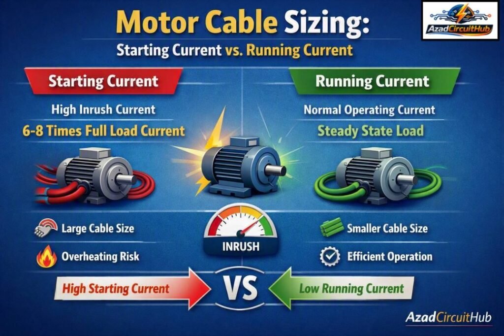
Table of Contents
Table of Contents
| Motor Cable Sizing Factor | Why It Matters |
|---|---|
| Full-load current | Determines the continuous load requirement |
| Starting current | Affects voltage drop during motor acceleration |
| Cable length | Longer circuits have greater voltage drop |
| Installation method | Changes cable ampacity |
| Ambient temperature | May require derating |
| Cable grouping | Reduces current-carrying capacity |
| Motor efficiency | Influences input current |
| Power factor | Affects operating current |
| Starting method | Changes starting current and duration |
| Permitted voltage drop | Helps prevent poor motor starting |
Running Current vs. Starting Current
Running current is the current a motor normally draws while operating at its rated load. It is commonly listed on the motor nameplate as full-load current. Starting current is the much higher current drawn when the motor is first energized.
A typical squirrel-cage induction motor may draw approximately 5 to 8 times its full-load current during direct-on-line (DOL) starting. Some motors can have even higher inrush current depending on their design.
| Motor Current | Typical Relationship to Full-Load Current | Duration |
|---|---|---|
| No-load current | 20–40% | Continuous |
| Normal running current | Around 100% | Continuous |
| Light overload | 100–125% | Short duration |
| DOL starting current | 500–800% | Few seconds |
| Soft starter current | Often 200–450% | Controlled |
| VFD starting current | Usually much lower | Controlled |
The important point is that the cable must carry the motor’s continuous operating current without exceeding its thermal rating. However, the starting condition must also be checked because high current creates temporary voltage drop.
Why Starting Current Matters for Cable Selection
A common mistake in motor cable sizing is assuming that the cable must be rated for the motor’s full starting current. That is generally not how conductor ampacity is selected.
If a motor has a 20 A full-load current and draws 120 A for several seconds during DOL starting, selecting a cable with a continuous ampacity of 120 A would usually be unnecessary. Instead, the cable is selected for the applicable continuous load and installation requirements, while the starting condition is checked for acceptable voltage drop and thermal performance.
High starting current becomes especially important when the motor is located far from the distribution panel. A long cable can develop significant voltage drop during acceleration.
For example, a motor may start normally when installed 20 m from the panel but struggle to accelerate when the same motor is installed 150 m away.
Planning an electrical motor circuit? Use our motor cable size calculator to quickly estimate conductor size from motor current, voltage, cable length, installation conditions, and voltage-drop requirements.
How to Calculate Motor Cable Size
A practical calculation starts with the motor nameplate data. For a three-phase motor, the approximate input current can be calculated using:
I = P × 1000 / (√3 × V × η × PF)
Where:
- I = motor current in amperes
- P = motor output power in kW
- V = line-to-line voltage
- η = motor efficiency
- PF = power factor
For a single-phase motor, the approximate equation is:
I = P × 1000 / (V × η × PF)
These equations provide an estimate. For final circuit design, the manufacturer’s nameplate current and applicable electrical code requirements should take priority.
Example: Three-Phase Motor
Consider a 15 kW, 400 V, three-phase motor with 90% efficiency and 0.85 power factor.
I = 15 × 1000 / (1.732 × 400 × 0.90 × 0.85)
The calculated current is approximately 28.3 A.
The actual nameplate FLC should then be checked before selecting the conductor.
| Parameter | Example Value |
|---|---|
| Motor power | 15 kW |
| Supply | 400 V, 3-phase |
| Efficiency | 90% |
| Power factor | 0.85 |
| Calculated current | 28.3 A |
| Starting current at 6× | About 170 A |
The 170 A starting current is temporary. It does not automatically mean the cable needs a 170 A continuous ampacity rating.
Voltage Drop During Motor Starting
Voltage drop is one of the most important parts of motor cable sizing, especially for long cable runs.
The voltage drop depends on conductor resistance, reactance, cable length, current, power factor, and circuit configuration. During startup, the current can rise dramatically, so the temporary voltage drop can also become much greater than the normal running voltage drop.
For a three-phase circuit, a simplified voltage-drop calculation is:
Vd = √3 × I × L × (R cos φ + X sin φ)
Where:
- Vd = voltage drop in volts
- I = current in amperes
- L = one-way cable length
- R = conductor resistance
- X = cable reactance
- φ = load power-factor angle
For simpler installations, resistance-based calculations may be sufficient for preliminary sizing, but industrial motor circuits should use appropriate cable data.
| Condition | Current | Voltage-Drop Concern |
|---|---|---|
| Motor running | Normal FLC | Normal design voltage drop |
| Motor starting DOL | 5–8× FLC | High temporary voltage drop |
| Soft starter | Reduced | Lower starting drop |
| VFD | Controlled | Usually easier to manage |
| Long feeder | Same motor current | Greater voltage drop |
Effect of Motor Starting Method
The motor starter has a direct effect on starting current. A DOL starter places the full supply voltage across the motor and usually produces the highest inrush current.
Star-delta starting reduces the current drawn from the supply during startup. Soft starters gradually increase voltage, while variable frequency drives (VFDs) control both frequency and voltage.
| Starting Method | Starting Current | Main Advantage |
|---|---|---|
| DOL | High | Simple and inexpensive |
| Star-delta | Lower than DOL | Reduced starting current |
| Soft starter | Controlled | Smooth acceleration |
| VFD | Highly controlled | Excellent starting control and speed control |
A lower starting current can reduce voltage sag, but it does not automatically permit a smaller conductor. Continuous ampacity, voltage drop, installation conditions, and code requirements still govern the final selection.
Cable Ampacity and Derating Factors
Motor cable sizing must also account for the environment in which the cable is installed. A conductor that can carry a certain current under reference conditions may have a lower permissible ampacity when installed in a hot or crowded location.
Important derating factors include:
- Ambient temperature
- Number of loaded conductors
- Cable grouping
- Conduit fill
- Installation method
- Soil thermal resistivity for buried cables
- Insulation temperature rating
- Enclosure temperature
- Continuous operating conditions
For example, several power cables installed tightly together may not dissipate heat as effectively as a single cable installed in free air.
| Installation Condition | Potential Effect |
|---|---|
| High ambient temperature | Reduces allowable ampacity |
| Multiple cables grouped together | Requires grouping correction |
| Buried cable | Soil conditions affect heat dissipation |
| Enclosed installation | May increase operating temperature |
| Free-air installation | Often provides better cooling |
| Long cable run | Increases voltage drop |
Copper vs. Aluminum Motor Cables
Copper and aluminum conductors can both be used for motor feeders when the cable, terminals, and installation are suitable.
Copper generally provides lower resistance for the same conductor size, while aluminum can offer a lower material cost and reduced weight. Because aluminum has higher resistivity, a larger conductor is often required to achieve similar electrical performance.
For long motor feeders, conductor resistance becomes particularly important because it affects both normal voltage drop and starting voltage drop.
Motor Cable Size Example
Suppose a 7.5 kW, 400 V three-phase motor has a nameplate full-load current of approximately 15 A. The motor is connected through a 100 m cable and uses DOL starting.
A basic design should not simply select a conductor based on 15 A. The designer should check:
- Motor nameplate current.
- Required conductor ampacity.
- Installation method.
- Ambient temperature.
- Cable grouping.
- Normal operating voltage drop.
- Starting voltage drop.
- Protective device coordination.
- Motor starter characteristics.
- Applicable electrical code.
If the voltage drop is excessive, increasing conductor cross-sectional area may be necessary even when the smaller conductor has sufficient ampacity.
Need to compare conductor options quickly? Check our motor cable size calculator for a faster starting point before verifying the final selection against cable manufacturer data and local electrical codes.
Cable Size and Motor Protection Are Different
Another common misunderstanding is treating cable size and overload protection as the same calculation.
The cable protects against excessive conductor heating, while the motor overload device protects the motor against sustained overload conditions. A circuit breaker or fuse also provides short-circuit and fault protection.
The overload setting is normally based on motor nameplate information and the applicable electrical standard, rather than simply matching the cable ampacity.
| Component | Primary Purpose |
|---|---|
| Motor cable | Safely carries operating current |
| Overload relay | Protects motor from sustained overload |
| Circuit breaker | Provides circuit and short-circuit protection |
| Fuse | Provides overcurrent and fault protection |
| Contactor | Switches motor power |
| VFD | Controls motor speed and starting |
This distinction is important because using a larger cable does not eliminate the need for correct motor overload protection.
Common Motor Cable Sizing Mistakes
Several errors appear repeatedly in motor installations.
Selecting Cable From Starting Current Alone
A cable does not normally need continuous ampacity equal to the motor’s peak starting current. Instead, check the permitted starting conditions and voltage drop.
Ignoring Cable Length
A short feeder and a 200 m feeder supplying the same motor can require different conductor sizes because voltage drop increases with length.
Using Only kW to Select Cable
Motor kW alone does not provide enough information. Voltage, efficiency, power factor, FLC, installation method, and cable length also matter.
Ignoring Derating
A cable with sufficient ampacity under reference conditions may become undersized after temperature and grouping corrections.
Choosing the Breaker First
The protective device and conductor must be coordinated. Selecting a breaker without checking cable ampacity and motor starting characteristics can cause nuisance tripping or inadequate protection.
Practical Motor Cable Sizing Checklist
Before finalizing a motor feeder, verify the following:
- Motor rated power
- Rated voltage
- Single-phase or three-phase supply
- Nameplate full-load current
- Starting method
- Starting current
- Cable length
- Conductor material
- Insulation type
- Installation method
- Ambient temperature
- Cable grouping
- Voltage-drop limit
- Short-circuit withstand requirements
- Overload protection
- Circuit breaker or fuse rating
- Local electrical code
For a quick conductor-size estimate, try our motor cable size calculator and then confirm the result with the motor manufacturer, cable data, and applicable electrical standards.
FAQs
1. Should motor cable size be based on starting current?
Not usually. The continuous cable ampacity is primarily selected from the motor’s operating current and applicable installation rules. Starting current should be checked separately for voltage drop, acceleration performance, and protective-device coordination.
2. How many times higher is motor starting current?
A DOL-started induction motor commonly draws around 5 to 8 times its full-load current. The actual value depends on motor design, load, voltage, and manufacturer specifications.
3. Does a longer motor cable require a larger cable?
It can. A longer cable has greater impedance and therefore greater voltage drop. Increasing conductor size may be necessary when the calculated voltage drop exceeds the permitted limit or causes starting problems.
4. Can a VFD reduce motor starting current?
Yes. A VFD can control motor voltage and frequency during acceleration, which generally produces a much lower and more controlled starting current than DOL starting.
5. What information is needed to calculate motor cable size?
The key information includes motor nameplate current, voltage, phase, cable length, conductor material, installation method, ambient conditions, cable grouping, starting method, and permitted voltage drop. Local electrical code requirements should also be checked before installation.
Final Takeaway
Motor cable sizing requires more than matching a conductor to the motor’s running current. The full-load current determines the basic continuous load requirement, while starting current becomes especially important when checking voltage drop and motor acceleration.
A reliable design considers the complete installation, including cable length, conductor material, temperature, grouping, starting method, protective devices, and applicable electrical standards. For short motor feeders, running-current requirements may dominate the selection. For long feeders, voltage drop can make a larger conductor necessary even when the smaller cable has adequate ampacity.
The safest approach is to calculate the cable requirement, verify both running and starting conditions, and then confirm the final selection using manufacturer data and the electrical code applicable to the installation.
Get new guides in your feed. Follow Electrical Insights on LinkedIn for new electrical standards guides, calculators and design tips from Azad Circuit Hub.
#MotorCableSizing, #MotorStartingCurrent, #MotorRunningCurrent, #MotorCables, #CableSizing, #ElectricalEngineering, #MotorProtection, #VoltageDrop, #ElectricalDesign, #IndustrialElectrical
