
Common Cable Tray Fill Mistakes (and How to Avoid Them)
Cable tray systems make cable installation easier, cleaner, and more accessible than many enclosed wiring methods. But a tray can still become overloaded, poorly arranged, or difficult to maintain if its fill is not calculated correctly. Many installation problems come from simple errors such as using the wrong cable dimensions, ignoring future capacity, or treating every tray type the same.
Understanding common cable tray fill mistakes helps engineers, electricians, and designers create safer and more practical cable routing systems. Proper cable tray sizing also improves heat dissipation, reduces installation problems, and leaves enough working space for future additions.
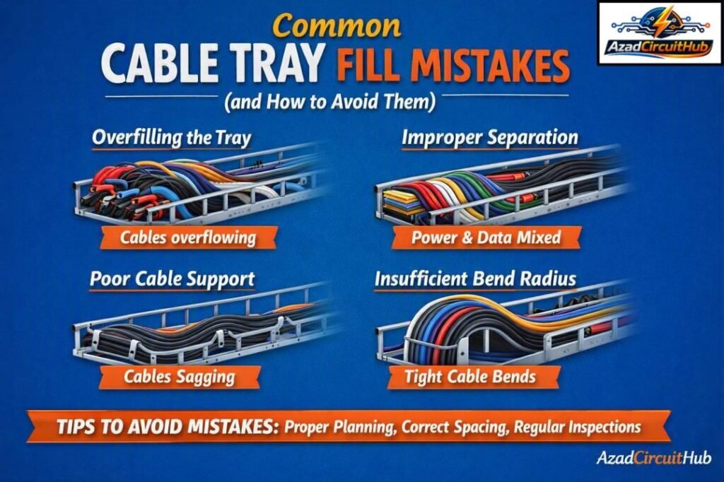
Table of Contents
Table of Contents
Quick Cable Tray Fill Guide
The following table provides a quick reference for the main factors that should be checked before selecting a tray.
| Check | What to Verify | Why It Matters |
|---|---|---|
| Cable outside diameter | Use the actual manufacturer’s dimensions | Determines occupied tray area |
| Number of cables | Count all installed cables | Prevents underestimating fill |
| Cable arrangement | Single layer or multi-layer | Changes usable tray capacity |
| Tray width | Select adequate clear width | Provides room for cable placement |
| Tray depth | Check against cable quantity and type | Prevents overcrowding |
| Cable spacing | Follow applicable standard and manufacturer guidance | Supports cooling and maintenance |
| Future capacity | Allow spare space | Makes future expansion easier |
| Cable weight | Check tray load rating | Prevents mechanical overloading |
| Tray type | Ladder, perforated, solid-bottom, etc. | Fill rules can differ |
| Installation conditions | Ambient temperature and grouping | Can affect ampacity |
Common Cable Tray Fill Mistakes at a Glance
| Mistake | Typical Result | Better Approach |
|---|---|---|
| Guessing cable dimensions | Incorrect fill calculation | Use manufacturer cable OD |
| Using conductor size as cable diameter | Major sizing error | Use complete cable outside diameter |
| Ignoring cable quantity | Tray becomes crowded | Count every cable |
| Filling the tray to its physical limit | Poor cooling and maintenance | Follow applicable fill criteria |
| Forgetting future cables | Expensive modifications later | Include spare capacity |
| Ignoring cable weight | Tray or supports may be overloaded | Check tray load rating |
| Mixing cable types without planning | Poor organization and heating concerns | Separate and arrange circuits properly |
| Ignoring fittings | Straight-run calculation becomes inaccurate | Include bends, tees, and transitions |
| Using one rule for every tray | Incorrect design | Apply the relevant standard |
| Failing to verify calculations | Installation changes become necessary | Review tray selection before procurement |
What Is Cable Tray Fill?
Cable tray fill refers to the amount of usable tray space occupied by cables. It is usually evaluated using cable cross-sectional area, cable diameter, cable arrangement, or the applicable requirements for the particular tray and installation.
The important point is that cable tray fill is not simply a matter of making cables physically fit inside the tray. The design must also consider heat dissipation, cable installation, maintenance access, mechanical loading, and future expansion.
For example, a tray may physically hold a large number of small cables, but that does not automatically mean the arrangement is suitable. Power cables, control cables, instrumentation cables, and communication cables may have different installation requirements.
1. Using Conductor Size Instead of Cable Outside Diameter
One of the most common cable tray fill mistakes is using the conductor cross-section as though it represents the complete cable size.
A 240 mm² conductor, for example, does not have an outside diameter of 240 mm. The finished cable includes insulation, screens, fillers, armor, bedding, and an outer sheath where applicable.
For tray fill calculations, use the manufacturer’s actual cable outside diameter. This is especially important for XLPE cables, armored cables, multicore cables, and large power cables.
| Cable Information | Suitable for Tray Fill? |
|---|---|
| Conductor cross-sectional area | No, not by itself |
| Insulation thickness | No, not by itself |
| Manufacturer’s outside diameter | Yes |
| Overall cable diameter including sheath | Yes |
| Estimated diameter from conductor size | Avoid where actual data is available |
2. Guessing the Cable Diameter
Another frequent mistake is using a standard or estimated cable diameter without checking the cable datasheet.
Two cables with the same conductor size can have different outside diameters because of differences in insulation, voltage rating, armor, sheath construction, and manufacturer design.
Always obtain cable dimensions from the actual product datasheet when possible.
This small step can significantly improve the accuracy of tray fill calculations.
3. Ignoring the Number of Cables
A tray calculation can become inaccurate if the designer considers only cable size and forgets the total number of cables.
For example, ten large cables require very different tray capacity from three cables of the same diameter. The cable schedule should therefore be available before final tray selection.
Create a simple cable schedule containing:
- Cable identification
- Cable type
- Number of cores
- Conductor size
- Overall diameter
- Cable length
- Cable weight
- Circuit type
- Installation arrangement
This makes the tray design easier to verify and update.
4. Treating Maximum Physical Capacity as Acceptable Fill
A tray may have enough physical space to hold additional cables, but using every available inch is poor practice.
Overcrowding makes cable pulling, dressing, inspection, testing, and replacement more difficult. It can also reduce ventilation around cables.
The applicable electrical code or standard should always be checked for the specific tray and cable arrangement.
A practical design should also consider maintenance and future expansion instead of aiming for the maximum possible physical occupancy.
5. Forgetting Future Expansion
One of the most costly cable tray fill mistakes occurs when a tray is designed only for today’s cables.
Industrial plants, commercial buildings, data centers, and renewable energy installations often expand. Additional feeders, control cables, communication cables, and instrumentation circuits may need to be installed later.
Leaving reasonable spare capacity can avoid tray replacement or the installation of additional parallel tray runs.
Before finalizing the design, ask:
- Will additional circuits be installed?
- Is the project expected to expand?
- Will spare cables be required?
- Is there room for another tray?
- Can future cables be installed without shutting down existing circuits?
For larger projects, using a cable tray sizing calculator can simplify the initial width selection and comparison of different tray sizes.
6. Ignoring Cable Weight and Tray Load
Cable tray fill is not only an electrical consideration. It is also a mechanical design issue.
A tray carrying several heavy armored cables can reach its load limit even when plenty of physical space remains.
Check the cable weight in kg/m or lb/ft and compare the total load with the tray manufacturer’s load rating.
| Parameter | Example |
|---|---|
| Number of cables | 12 |
| Cable weight | 4 kg/m each |
| Total cable weight | 48 kg/m |
| Tray and accessories | Add separately |
| Design load | Include applicable safety margin |
Support spacing must also be checked. A tray that is adequately sized in width may still require closer supports if the cable load is high.
7. Ignoring Cable Arrangement
Cable arrangement can have a major effect on tray utilization.
A group of single-core cables may require a different arrangement from multicore cables. Three-phase circuits may also need to be grouped correctly to maintain suitable magnetic and thermal conditions.
Avoid randomly stacking cables simply because they fit.
Consider:
- Cable diameter
- Number of circuits
- Single-core versus multicore construction
- Power versus control cables
- Heat-producing circuits
- Required separation
- Manufacturer recommendations
- Applicable electrical standards
Proper cable management is usually easier when circuits are planned before installation rather than sorted after the tray is full.
8. Forgetting Tray Fittings and Changes in Direction
Straight tray sections are easy to calculate, but real installations rarely consist entirely of straight runs.
Bends, tees, reducers, crosses, vertical risers, and transitions can change cable arrangement and usable space. Large cables also need adequate bending space at directional changes.
The cable minimum bend radius must be checked independently from tray fill.
| Tray Feature | Design Consideration |
|---|---|
| Straight section | Cable quantity and usable width |
| 90° bend | Cable bend radius |
| Tee | Cable routing and congestion |
| Reducer | Cable transition and spacing |
| Vertical bend | Cable support and radius |
| Riser | Cable weight and cleating |
| Cross fitting | Cable separation and arrangement |
A tray that looks adequate on the plan may become difficult to install around fittings if these areas are not reviewed.
9. Applying the Same Fill Rule to Every Cable Tray
Not every tray installation should be designed using the same calculation method.
Ladder trays, ventilated troughs, solid-bottom trays, and channel-type systems have different physical characteristics. Cable type and arrangement can also affect the applicable requirements.
Always identify the governing standard before calculating tray capacity. Depending on the project, this may involve NEC requirements, IEC standards, NEMA guidance, local electrical regulations, or project specifications.
Do not copy a tray fill percentage from another project without checking whether the same design conditions apply.
10. Mixing Power and Control Cables Without a Plan
Cable tray systems often carry several types of circuits. Poor separation can create installation, maintenance, and electromagnetic interference concerns.
High-voltage power cables, sensitive instrumentation cables, communication cables, and control wiring should be routed according to the applicable project and manufacturer requirements.
Where separation is required, consider:
- Separate trays
- Physical dividers
- Dedicated compartments
- Proper cable grouping
- Adequate spacing
- Shielding requirements
The correct solution depends on the cable types and system design.
How to Calculate Cable Tray Fill
A basic area-based approach can be used when the applicable standard permits it.
For a round cable, the approximate cross-sectional area is:
Cable Area = π × D² / 4
Where:
- D = outside diameter of the cable
- Cable Area = approximate cross-sectional area
For multiple identical cables:
Total Cable Area = Number of Cables × Cable Area
The required tray area can then be compared with the allowable usable tray area based on the applicable requirements.
For example, if a cable has an outside diameter of 20 mm:
Cable area ≈ 3.1416 × 20² / 4
Cable area ≈ 314 mm²
For 20 identical cables:
Total area ≈ 6,280 mm²
This simplified calculation is useful for understanding the principle, but the final design should follow the governing code, cable arrangement, tray manufacturer’s data, and project specifications.
Cable Tray Fill Calculation Checklist
Use this checklist before approving a tray layout.
| Step | Design Check |
|---|---|
| 1 | Obtain the cable schedule |
| 2 | Confirm actual cable outside diameters |
| 3 | Count the cables in each tray section |
| 4 | Identify cable types and voltage levels |
| 5 | Determine the permitted calculation method |
| 6 | Calculate cable occupancy |
| 7 | Select an appropriate tray width |
| 8 | Check tray depth and arrangement |
| 9 | Verify cable weight |
| 10 | Check support spacing |
| 11 | Review bends and fittings |
| 12 | Allow for future expansion |
| 13 | Check cable ampacity and grouping |
| 14 | Verify manufacturer’s tray rating |
| 15 | Review the completed layout |
For projects with many circuits, a cable tray sizing calculator can help compare cable quantities, cable diameters, tray widths, and available capacity before finalizing the design.
Practical Ways to Avoid Cable Tray Fill Mistakes
Good tray design starts before the first cable is installed. The following practices can prevent most sizing problems:
Use Manufacturer Data
Never rely on generic cable dimensions when accurate product data is available. Cable diameter and weight should come directly from the manufacturer’s datasheet.
Keep the Cable Schedule Updated
If a cable changes from 4-core to 3-core, or the conductor size changes during procurement, update the tray calculation.
Check the Heaviest Tray Section
Do not size the entire system only from an average cable count. One tray section may carry substantially more cables than another.
Review Installation Drawings
Check horizontal runs, vertical risers, bends, tees, equipment entries, and transitions. Congestion often occurs at these points.
Consider Future Loads
A small amount of spare capacity during initial construction can be far cheaper than installing another tray later.
Verify the Final Design
A second engineering review can identify errors in cable dimensions, tray width, support loading, and circuit arrangement before materials are ordered.
Cable Tray Fill vs Cable Conduit Fill
Cable tray and conduit fill are related concepts, but they should not be treated as interchangeable.
Conduit fill generally deals with cables or conductors occupying the internal cross-sectional area of a raceway. Cable tray design can involve cable arrangement, tray type, cable diameter, cable weight, heat dissipation, support spacing, and other factors.
| Feature | Cable Tray | Conduit |
|---|---|---|
| Installation access | Generally easy | More restricted |
| Cable pulling | Usually easier | Can be difficult with high fill |
| Heat dissipation | Often favorable with ventilated designs | More enclosed |
| Cable arrangement | Important | More constrained |
| Mechanical loading | Important | Different design considerations |
| Future additions | Often easier | May require spare conduit capacity |
| Fill calculation | Depends on tray/cable arrangement | Governed by applicable raceway rules |
Understanding this difference prevents engineers from transferring conduit fill assumptions directly into tray design.
Final Cable Tray Design Tips
Avoiding cable tray fill mistakes is mainly about using accurate data and reviewing the complete installation rather than focusing only on tray width.
Before approving a design, verify the actual cable outside diameter, cable quantity, cable arrangement, cable weight, support spacing, bend radius, tray type, and applicable electrical standard. Also consider future circuits and maintenance access.
For complex installations, calculate each tray section separately. A single tray width may not be suitable for every part of a project.
When several tray options need to be compared, a cable tray sizing calculator can make the preliminary design faster and help identify a suitable tray width before detailed engineering.
FAQs About Cable Tray Fill
What is the most common cable tray fill mistake?
One of the most common errors is using conductor size instead of the actual finished cable outside diameter. The complete cable diameter should be obtained from the manufacturer because insulation, armor, screens, and sheathing can significantly increase the overall size.
How much cable can I put in a cable tray?
The permitted cable occupancy depends on the tray type, cable arrangement, cable construction, and applicable standard. Do not assume that filling the entire physical tray area is acceptable. Check the relevant code, manufacturer instructions, and project specifications.
Does cable tray fill affect cable ampacity?
It can. Cable grouping, spacing, ambient temperature, and installation arrangement may affect heat dissipation and ampacity. The applicable ampacity requirements should therefore be checked separately from the physical tray capacity calculation.
Should I leave spare capacity in a cable tray?
Yes, where practical. Spare capacity provides room for future circuits and makes maintenance or system expansion easier. The amount of spare space should be based on the project requirements and expected future loads rather than an arbitrary percentage.
Can I use conduit fill rules for cable tray sizing?
No. Conduit fill rules should not automatically be applied to cable tray systems. Tray design has its own requirements based on tray construction, cable arrangement, loading, spacing, and the governing electrical standard.
Get new guides in your feed. Follow Electrical Insights on LinkedIn for new electrical standards guides, calculators and design tips from Azad Circuit Hub.
#CableTrayFill, #CableTrayMistakes, #CableTraySizing, #CableManagement, #ElectricalEngineering, #NEC, #CableInstallation, #ElectricalDesign, #CableTrayCapacity, #ElectricalSafety
