
NEC 392.22(A) Multiconductor Cable Tray Fill Rules
If you install power or control cables in cable trays, understanding NEC 392.22(A) is essential. This section explains how multiconductor cables should be arranged inside cable trays to maintain safety, proper heat dissipation, and code compliance. Incorrect tray fill can lead to overheating, difficult maintenance, and failed inspections.
Before calculating allowable tray capacity, it is useful to understand the code requirements for multiconductor cable installations. This guide explains NEC 392.22(A) in simple language with practical examples, tables, and design tips.
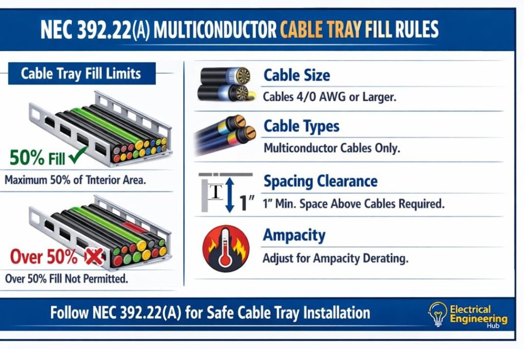
Table of Contents
Table of Contents
| Quick Reference | Details |
|---|---|
| NEC Section | NEC 392.22(A) |
| Applies To | Multiconductor cables in cable trays |
| Primary Purpose | Safe cable tray fill and heat dissipation |
| Installation Method | Single layer or multiple layers depending on cable type and tray design |
| Common Applications | Industrial plants, substations, commercial buildings, data centers |
| Related Standard | NEC Article 392 |
Before performing any fill calculation, use our Cable Tray Fill Calculator according to NEC to determine the allowable cable quantity based on the latest NEC requirements.
What is NEC 392.22(A)?
NEC 392.22(A) provides the fill requirements for multiconductor cables installed inside cable trays. The rule limits how much of the tray can be occupied by cables while ensuring sufficient airflow for cooling.
Unlike conduit fill calculations, cable tray fill is generally based on the total cable cross-sectional area and the inside width of the tray. The acceptable fill depends on cable size, insulation type, and installation arrangement.
The objective is to:
- Prevent cable overheating
- Improve heat dissipation
- Reduce mechanical stress
- Simplify future cable additions
- Maintain safe operating temperatures
These requirements are widely followed in industrial power distribution systems where large numbers of multiconductor cables are routed together.
What Are Multiconductor Cables?
A multiconductor cable contains two or more insulated conductors enclosed within one overall jacket.
Common examples include:
| Cable Type | Typical Application |
|---|---|
| Control cables | PLC and automation systems |
| Instrumentation cables | Process plants |
| Low-voltage power cables | Industrial distribution |
| Medium-voltage cables | Utility installations |
| VFD cables | Motor control |
Because these cables already have an overall jacket, they are treated differently from individual single conductors installed in cable trays.
NEC 392.22(A) Multiconductor Cable Fill Rules Explained
NEC 392.22(A) establishes how multiconductor cables must be installed in cable trays based on the cable size and the tray type. The objective is to prevent excessive heat buildup while ensuring cables remain accessible for inspection and future maintenance.
The Code does not allow installers to simply fill every available space in a cable tray. Instead, the allowable fill depends on the cable’s outside diameter and whether the cables are installed in a ventilated or solid-bottom cable tray.
The following table summarizes the NEC 392.22(A) Multiconductor Cable Tray Fill Rules.
| NEC 392.22(A) Requirement | Explanation |
|---|---|
| Fill is based on cable outside diameter (OD) | Always use the manufacturer’s published overall diameter instead of conductor size. |
| Tray width determines cable capacity | Wider trays provide greater usable fill area and better cooling. |
| Cable spacing is important | Cables should be arranged to promote natural air circulation. |
| Heat dissipation must not be restricted | Overfilled trays reduce airflow and increase operating temperature. |
| Future cable additions should be considered | Leave spare tray capacity whenever practical. |
These requirements are intended to maintain cable ampacity while extending insulation life.
Rule 1 – Multiconductor Cables 4/0 AWG and Larger
One of the most important provisions within NEC 392.22(A) applies to larger multiconductor power cables.
When multiconductor cables contain conductors that are 4/0 AWG or larger, they are generally installed in a single layer within the cable tray. Stacking large cables in multiple layers restricts airflow and increases the cable operating temperature.
Single-layer installation provides several advantages:
- Better cooling around each cable
- Lower conductor operating temperature
- Easier cable identification
- Reduced mechanical stress
- Simpler future maintenance
Large industrial feeders, generator cables, and transformer feeders commonly fall into this category.
| Requirement | Reason |
|---|---|
| Single-layer installation | Improves heat dissipation |
| Avoid excessive stacking | Prevents overheating |
| Maintain cable support | Reduces insulation damage |
Rule 2 – Multiconductor Cables Smaller Than 4/0 AWG
Smaller multiconductor cables provide greater flexibility during installation.
Since these cables generate less heat individually, NEC permits them to be installed in multiple layers provided the allowable tray fill requirements are not exceeded.
Examples include:
- Control cables
- Instrumentation cables
- Low-voltage feeder cables
- Automation cables
- Building service cables
Although multiple layers are permitted, installers should avoid tightly compressing the cables together because restricted airflow reduces cooling efficiency.
Rule 3 – Cable Fill Area Must Not Exceed NEC Limits
Another important requirement is that the combined cross-sectional area of all installed cables must remain within the allowable cable tray fill.
This calculation uses the outside diameter of every cable rather than the conductor size inside the cable.
The general calculation process is:
- Obtain the outside diameter (OD) of each cable from the manufacturer.
- Calculate the cross-sectional area of each cable.
- Add the areas of all cables.
- Compare the total cable area with the maximum allowable fill for the selected tray.
This approach produces a much more accurate tray design than estimating cable quantity.
Before performing manual calculations, you can verify the installation using the Cable Tray Fill Calculator according to NEC, which automatically checks tray capacity based on NEC requirements.
Rule 4 – Ventilated vs Solid-Bottom Cable Trays
The type of cable tray also affects cable cooling.
Ventilated ladder trays and ventilated trough trays allow heat to escape through the openings, making them the preferred choice for power distribution systems.
Solid-bottom trays restrict natural ventilation and are generally selected when additional protection from dust, moisture, or falling debris is required.
| Tray Type | Cooling Performance | Typical Application |
|---|---|---|
| Ladder tray | Excellent | Power distribution |
| Ventilated trough | Very good | Industrial plants |
| Solid-bottom tray | Moderate | Sensitive control wiring |
Proper tray selection improves cable life and reduces operating temperatures.
Rule 5 – Follow Manufacturer Installation Requirements
While NEC provides the minimum code requirements, cable manufacturers may specify additional installation limitations.
These recommendations often include:
- Minimum bending radius
- Maximum pulling tension
- Support spacing
- Stacking limitations
- Ambient temperature corrections
Whenever manufacturer instructions are more restrictive than the NEC minimum requirements, the manufacturer’s instructions should be followed.
Rule 6 – Allow Space for Future Expansion
Experienced electrical designers rarely fill a cable tray to its maximum permitted capacity.
Instead, they reserve spare tray space for future equipment additions.
Maintaining reserve capacity offers several benefits:
- Easier installation of future cables
- Reduced project costs during expansion
- Better airflow
- Improved maintenance access
- Lower risk of cable damage during modifications
Many industrial facilities intentionally reserve 20% to 30% spare tray space as a design practice, although the NEC itself does not mandate a specific expansion percentage.
Basic Fill Requirements
The following table summarizes the general principles found in NEC 392.22(A).
| Requirement | Purpose |
|---|---|
| Maintain allowable tray fill | Prevent overheating |
| Use cable outside diameter | Accurate fill calculation |
| Do not exceed permitted area | Ensure code compliance |
| Arrange cables properly | Improve airflow |
| Support cables evenly | Reduce mechanical damage |
These requirements become even more important when large industrial cable trays carry hundreds of power and control cables.
Why Tray Fill Matters
Many engineers focus only on cable ampacity while overlooking tray fill limitations.
An overloaded cable tray creates several problems.
| Problem | Result |
|---|---|
| Reduced airflow | Higher cable temperature |
| Excessive cable weight | Tray structural loading |
| Difficult maintenance | Longer shutdowns |
| Limited expansion | Costly future modifications |
| Poor organization | Increased troubleshooting time |
Proper tray fill helps maintain both electrical safety and long-term reliability.
Factors That Affect Cable Tray Fill
Several variables influence the allowable number of multiconductor cables.
Cable Diameter
Larger cable diameters occupy more tray area.
Even a small increase in cable diameter significantly reduces the number of cables that fit inside the tray.
Tray Width
Wider trays provide greater usable cable area.
Designers often select wider trays instead of increasing tray depth because wider trays improve cooling.
Cable Arrangement
Organized cable placement produces better airflow than random stacking.
Neatly arranged cables also simplify identification and maintenance.
Future Expansion
Industrial facilities frequently add equipment after commissioning.
Leaving spare tray capacity avoids expensive tray modifications later.
Example Calculation
Suppose an industrial project uses:
| Parameter | Value |
|---|---|
| Tray Width | 24 inches |
| Cable Type | Multiconductor |
| Cable Outside Diameter | 1.2 inches |
| Quantity Required | 42 cables |
The engineer first determines the total occupied cable area.
Next, the allowable fill area specified by NEC 392.22(A) is compared with the required cable area.
If the occupied area exceeds the allowable limit, one of the following changes is required:
- Increase tray width
- Install an additional tray
- Redistribute cables
- Select a larger tray size
For quick verification, use the Cable Tray Fill Calculator according to NEC before finalizing tray layouts.
Installation Best Practices
Following good engineering practices improves both safety and long-term system performance.
| Best Practice | Benefit |
|---|---|
| Keep similar cables together | Easier maintenance |
| Separate power and instrumentation | Reduced interference |
| Label cable groups | Faster troubleshooting |
| Maintain bending radius | Prevent insulation damage |
| Leave spare tray capacity | Future expansion |
These practices are commonly followed in power plants, refineries, manufacturing facilities, and commercial buildings.
Common Mistakes
Many installation problems occur because designers misunderstand NEC 392.22(A).
Avoid these common errors.
| Mistake | Possible Consequence |
|---|---|
| Filling tray completely | Excessive heating |
| Ignoring cable diameter | Incorrect fill calculation |
| Mixing cable types improperly | Reduced organization |
| Using outdated code editions | Inspection failure |
| No allowance for future cables | Expensive upgrades |
Careful planning during the design stage eliminates these issues.
NEC 392.22(A) vs Conduit Fill Rules
Cable tray fill requirements differ from conduit fill requirements.
| Cable Tray | Conduit |
|---|---|
| Open ventilation | Enclosed raceway |
| Better heat dissipation | Higher heat buildup |
| Easier cable additions | Limited spare capacity |
| Area-based fill rules | Percentage fill rules |
| Suitable for large cable systems | Suitable for smaller routing |
Understanding these differences helps engineers select the appropriate wiring method for each project.
Industries That Commonly Use NEC 392.22(A)
Multiconductor cable tray systems are widely installed in:
- Manufacturing plants
- Oil and gas facilities
- Solar power plants
- Data centers
- Water treatment plants
- Chemical industries
- Utility substations
- Commercial buildings
Large facilities often contain thousands of feet of cable trays carrying power, control, communication, and instrumentation cables.
Inspection Checklist
Before project handover, verify the following items.
| Inspection Item | Status |
|---|---|
| Tray fill within NEC limits | ✓ |
| Cable support adequate | ✓ |
| Cable identification complete | ✓ |
| Proper tray width selected | ✓ |
| Future expansion space available | ✓ |
| No cable damage observed | ✓ |
This checklist helps reduce inspection findings and improves installation quality.
Related Guides & Tools
- Cable Tray Fill Calculator (NEC 392)
- NEC 392.22(A)(1)(a) Explained
- NEC 392.22(B) Single Conductor Cable Tray Fill Rules
Frequently Asked Questions
Does NEC 392.22(A) apply to all cable trays?
It applies to multiconductor cables installed in cable tray systems covered by NEC Article 392.
Why is tray fill limited?
Limiting tray fill improves airflow, prevents overheating, and ensures safe cable operation.
Can different multiconductor cables share the same tray?
Yes, provided the installation complies with NEC requirements and any applicable separation requirements.
Is tray width more important than tray depth?
In many industrial installations, increasing tray width provides better cable organization and cooling than increasing tray depth
Conclusion
Understanding nec 392.22(a) multiconductor cables is essential for designing safe, efficient, and code-compliant cable tray systems. Proper tray fill improves cable cooling, simplifies maintenance, supports future expansion, and helps prevent inspection issues. Engineers should always calculate tray occupancy carefully instead of estimating available space.
Before completing any cable tray design, verify the installation using the Cable Tray Fill Calculator according to NEC. A proper calculation ensures compliance with NEC Article 392 while improving the long-term reliability and safety of the electrical installation.
Follow Us on Social:
Subscribe our Newsletter on Electrical Insights for latest updates from Electrical Engineering Hub
NEC39222A, #CableTrayFillRules, #MulticonductorCable, #NECCode, #CableTray, #ElectricalEngineering, #ElectricalCode, #NECCompliance, #IndustrialElectrical, #ElectricalDesign
