
NEC vs IEC 61537 Cable Tray Fill Rules Compared
Cable tray design is not simply a matter of choosing a tray wide enough to hold the cables. The available space, cable arrangement, heat dissipation, installation method, mechanical loading, and applicable electrical code all affect the final selection. This is especially important when comparing U.S. installations governed by the National Electrical Code (NEC) with projects that use IEC-based standards.
The key point in the NEC vs IEC 61537 Cable Tray Fill comparison is that the two systems approach cable tray design differently. NEC Article 392 provides specific electrical installation requirements, including conductor and cable fill provisions. IEC 61537, by contrast, primarily establishes requirements and tests for cable tray and cable ladder systems themselves. It does not provide one universal cable-fill percentage that applies to every installation.
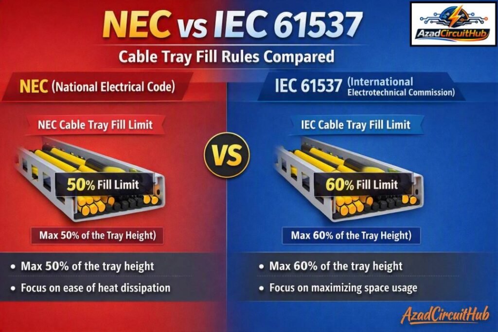
Table of Contents
Table of Contents
Quick Comparison: NEC vs IEC 61537 Cable Tray Fill
| Design factor | NEC approach | IEC 61537 approach |
|---|---|---|
| Main reference | NEC Article 392 | IEC 61537 |
| Primary purpose | Electrical installation requirements | Cable tray and cable ladder system requirements |
| Universal tray fill percentage | No single percentage for every condition | No universal percentage specified |
| Cable/conductor arrangement | Important to fill calculation | Considered as part of system application and installation design |
| Ampacity impact | Yes, through NEC requirements | Determined by applicable installation and cable standards |
| Tray mechanical performance | Addressed through NEC installation requirements and listed equipment | Major focus of IEC 61537 testing and classification |
| Loading | Cable weight and support must be considered | System load-carrying capability is a major requirement |
| Corrosion/environment | Installation requirements apply | Environmental and material performance are addressed |
| Best use | U.S. electrical installations | IEC-based international projects |
What Is the NEC Cable Tray Fill Rule?
The NEC addresses cable tray systems primarily in Article 392. The actual allowable fill depends on the type and number of conductors or cables, their construction, and the type of tray.
This is an important point when applying the NEC vs IEC 61537 Cable Tray Fill approach. You should not assume that one percentage can be used for every tray.
For example, NEC 392.22 provides rules for determining the allowable area occupied by conductors and cables in cable trays. Different provisions apply to multiconductor cables, single-conductor cables, and other cable arrangements.
The tray type also matters. A ventilated tray, ladder tray, or solid-bottom tray may have different requirements depending on the cable arrangement and installation conditions.
Common NEC Cable Tray Fill Considerations
| Item | Why it matters |
|---|---|
| Number of cables | The allowable occupied area can change |
| Cable outside diameter | Used to determine physical cable area |
| Cable type | Multiconductor and single-conductor installations are treated differently |
| Tray width | Determines usable installation space |
| Tray depth | Affects physical capacity and arrangement |
| Tray construction | Ventilated, ladder, and solid-bottom designs can have different requirements |
| Cable ampacity | Heat buildup and conductor grouping can affect allowable current |
| Cable weight | Must be checked against tray load capacity |
| Future cables | Spare capacity may be desirable for expansion |
For an actual project, always use the edition of the NEC adopted by the authority having jurisdiction (AHJ). Local amendments can also change how requirements are applied.
Does IEC 61537 Specify a Cable Tray Fill Percentage?
No. This is one of the most important differences in the NEC vs IEC 61537 Cable Tray Fill discussion.
IEC 61537 is titled Cable management — Cable tray systems and cable ladder systems. Its primary purpose is to establish requirements and tests for cable tray and cable ladder systems, including mechanical strength, electrical continuity where applicable, resistance to corrosion, and other characteristics.
It does not function like an NEC table that gives a universal maximum cable area percentage for every cable tray installation.
Therefore, an engineer working on an IEC-based project normally needs to consider IEC 61537 together with the applicable cable, wiring, installation, thermal, and project standards.
A project specification may impose a maximum tray occupancy such as 40% or 50%, but that project limit should not automatically be described as an IEC 61537 requirement.
NEC vs IEC 61537 Cable Fill: The Main Difference
The simplest way to understand the NEC vs IEC 61537 Cable Tray Fill difference is to look at what each standard is trying to accomplish.
The NEC is an electrical installation code. Article 392 contains rules that govern how cable tray systems can be used for conductors and cables.
IEC 61537 is primarily a product and system standard for cable trays and cable ladders. It establishes performance requirements and testing methods so that the tray system can safely support and manage cables.
This distinction prevents a common design mistake: treating IEC 61537 as though it contains a direct equivalent of every NEC cable-tray fill rule.
How to Calculate Cable Tray Fill
A basic physical tray-fill calculation starts by determining the cross-sectional area of each cable.
For a round cable, the approximate area is:
Cable area = π × (D/2)²
Where:
- D = cable outside diameter
- π = approximately 3.1416
The total cable area is then compared with the allowable tray area under the applicable design rule.
For example, suppose a project contains ten cables with an outside diameter of 20 mm. The approximate area of one cable is:
3.1416 × (20/2)² = 314.16 mm²
The combined cable area is:
314.16 × 10 = 3,141.6 mm²
That number alone does not prove that the tray is acceptable. The engineer must still determine the applicable fill limit, cable arrangement, tray dimensions, ampacity requirements, support spacing, and loading.
For faster sizing, use a cable tray fill calculator to compare the total cable area with the usable tray area before selecting the tray width and depth.
Cable Tray Fill Example
Consider a tray with an internal width of 300 mm and an internal depth of 50 mm. Its simple rectangular cross-sectional area is:
300 × 50 = 15,000 mm²
Suppose the cables occupy 6,000 mm².
The physical occupancy is:
6,000 ÷ 15,000 × 100 = 40%
This 40% figure is a useful physical calculation, but it should not automatically be treated as an approved NEC or IEC 61537 limit.
The applicable code or project specification must determine whether the installation is acceptable.
A cable tray fill calculator can make these calculations easier when a project contains multiple cable sizes and large cable schedules.
Why Cable Tray Fill Matters
Cable tray fill is more than a space-management issue. Excessive cable concentration can create practical problems during installation and operation.
Important considerations include:
- Heat dissipation: Closely grouped cables can affect heat transfer and ampacity.
- Cable installation: Overcrowded trays make pulling, routing, and identification more difficult.
- Maintenance: Technicians need access to individual cables.
- Future expansion: Completely full trays leave little room for additional circuits.
- Mechanical loading: More cables increase the weight placed on the tray.
- Bending radius: Large cables require adequate space for compliant bends.
- Segregation: Power, control, instrumentation, and communication cables may require separation.
- Fire and safety considerations: Project requirements may restrict cable grouping or tray occupancy.
These factors are particularly relevant when using the NEC vs IEC 61537 Cable Tray Fill methodology on large industrial installations.
NEC and IEC Cable Tray Design Checklist
| Check | NEC project | IEC-based project |
|---|---|---|
| Cable area | Check NEC Article 392 | Follow project and applicable installation requirements |
| Tray construction | Verify permitted tray type | Verify IEC 61537-compliant system |
| Cable ampacity | Apply NEC ampacity rules | Apply applicable IEC cable/installation requirements |
| Tray load | Verify rated capacity | Verify IEC 61537 mechanical performance |
| Support spacing | Follow NEC and manufacturer requirements | Follow manufacturer and project requirements |
| Earthing/bonding | Apply NEC requirements | Apply applicable IEC requirements |
| Cable segregation | Check applicable NEC provisions | Check project and IEC requirements |
| Corrosion protection | Select suitable listed equipment | Check IEC system classification and environment |
| Future capacity | Recommended during design | Normally established by project specification |
| AHJ/project approval | Required | Required by project authority |
Common Mistakes in Cable Tray Fill Calculations
One frequent mistake is measuring the cable by conductor size instead of its actual outside diameter. Cable tray fill is based on the physical space occupied by the cable, so the manufacturer’s cable diameter is normally the appropriate starting point.
Another mistake is using the same fill percentage for every installation. NEC requirements vary according to the cable and tray arrangement, while IEC 61537 itself does not establish one universal occupancy percentage.
Designers should also avoid ignoring cable weight. A tray that has enough physical space may still exceed its allowable load when filled with heavy power cables.
Finally, do not use physical fill as a substitute for ampacity calculations. Tray capacity and electrical loading are separate checks.
NEC vs IEC 61537 Cable Fill for Industrial Projects
Large industrial projects often contain power cables, control cables, instrumentation cables, fiber-optic cables, and communication circuits. These systems may require different routing strategies even when they occupy the same tray system.
In an NEC installation, Article 392 should be checked alongside the relevant requirements for conductor ampacity, grounding, overcurrent protection, and cable installation.
In an IEC-based installation, IEC 61537 should be considered as part of the cable management system design, while other applicable IEC standards and project specifications govern cable selection, installation, thermal performance, segregation, and electrical safety.
This makes the NEC vs IEC 61537 Cable Tray Fill comparison particularly important for multinational projects. A design that complies with one system should not automatically be assumed to comply with the other.
For projects with many cable sizes, using a cable tray fill calculator can reduce manual calculations and help identify undersized trays early in the design process.
Which Standard Should You Use?
The answer depends on the project jurisdiction and contractual requirements.
For a U.S. installation, the adopted NEC edition and local electrical requirements should be the starting point. For an IEC-based international project, IEC 61537 may define the required cable tray system characteristics, but additional standards and project specifications will normally be necessary for the complete installation design.
If a project specification states a maximum tray occupancy, that requirement should be followed even when it is more conservative than the general engineering practice.
Always verify the final design against the applicable code, manufacturer documentation, and AHJ requirements.
FAQs
1. What is the NEC cable tray fill percentage?
There is no single NEC percentage that applies to every cable tray installation. NEC Article 392.22 contains different fill provisions depending on cable type, number of cables, conductor arrangement, and tray construction.
2. Does IEC 61537 have a 40% cable tray fill rule?
No. IEC 61537 does not establish a universal 40% cable occupancy requirement. A 40% or 50% limit may come from a project specification, engineering standard, or another applicable requirement.
3. Is NEC Article 392 used for cable tray sizing?
Yes. NEC Article 392 contains requirements for cable tray systems, including provisions relevant to conductor and cable fill. Other NEC articles may also affect the complete installation.
4. How do I calculate cable tray fill?
Determine the outside diameter and cross-sectional area of each cable, total the cable areas, and compare the result with the applicable tray-fill requirement. Then separately check ampacity, cable arrangement, tray loading, support spacing, and other installation requirements.
5. Can I use the same cable tray fill calculation for NEC and IEC projects?
Not automatically. The physical cable-area calculation is similar, but the governing requirements can differ. The NEC vs IEC 61537 Cable Tray Fill comparison shows why the applicable code, IEC requirements, project specification, and local authority requirements must be reviewed before final tray selection.
Get new guides in your feed. Follow Electrical Insights on LinkedIn for new electrical standards guides, calculators and design tips from Azad Circuit Hub.
#NEC, #IEC61537, #CableTray, #CableTrayFill, #ElectricalEngineering, #CableManagement, #ElectricalCodes, #CableTrayDesign, #NECStandards, #IECStandards
