Load Flow vs Short Circuit vs Fault Current Analysis: Complete Power System Comparison
Understanding the difference between load flow, short circuit, and fault current studies is essential for designing and operating a safe electrical power system. These studies use different inputs, calculations, and objectives, even though they are often performed using the same power system model.
For engineers comparing load flow vs short circuit analysis, the main difference is simple: load flow evaluates normal operating conditions, while short circuit and fault current studies evaluate abnormal conditions caused by electrical faults.
Quick Comparison: Load Flow vs Short Circuit vs Fault Current Analysis
| Parameter | Load Flow Analysis | Short Circuit Analysis | Fault Current Analysis |
|---|---|---|---|
| Main purpose | Evaluate normal system operation | Calculate fault currents | Determine available fault current |
| Operating condition | Normal | Abnormal/faulted | Abnormal/faulted |
| Main outputs | Voltage, current, MW, MVAR, power factor | Fault current, fault MVA, voltage during fault | Available fault current at equipment location |
| Typical faults | Not applicable | 3-phase, L-G, L-L, L-L-G | Ground and phase faults |
| Main equipment checked | Transformers, cables, generators, buses | Breakers, relays, switchgear | Breakers, panels, fuses, equipment |
| Common standards | IEC 60909, ANSI/IEEE methods | IEC 60909, ANSI/IEEE | IEC 60909, ANSI/IEEE |
| Typical software | ETAP, SKM, EasyPower, PowerFactory | ETAP, SKM, EasyPower, PowerFactory | ETAP, SKM, EasyPower, PowerFactory |
| Key design question | Can the system operate correctly? | What happens during a fault? | How much fault current is available? |
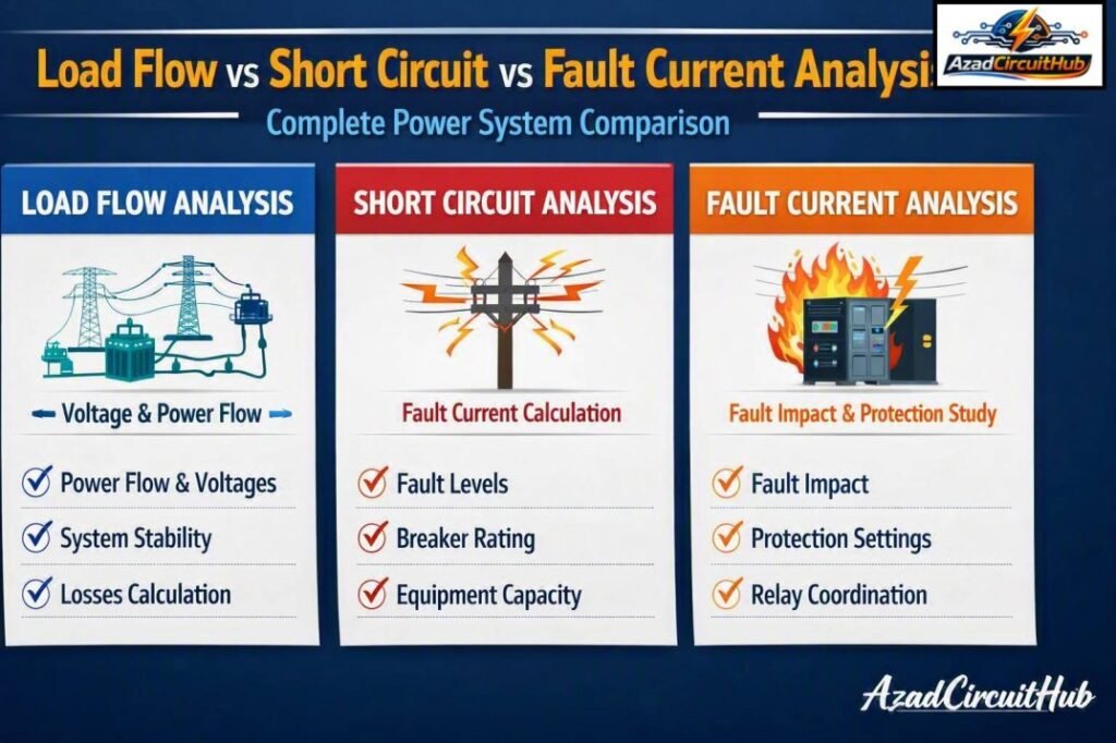
Table of Contents
Table of Contents
What Is Load Flow Analysis?
Load flow analysis, also called power flow analysis, determines how electrical power moves through a power system under normal operating conditions.
The study calculates bus voltages, voltage angles, real power flow, reactive power flow, branch currents, transformer loading, generator output, and system losses.
Typical load flow studies use:
- Bus voltage and voltage angle
- Generator MW and MVAR
- Transformer ratings and impedance
- Cable and transmission-line impedance
- Load demand
- Power factor
- Tap changer settings
- Shunt capacitors and reactors
- Utility grid parameters
The main objective is to verify that the system can supply connected loads without unacceptable voltage drops, excessive equipment loading, or poor power factor.
For example, a 132 kV industrial substation may have several transformers, motors, feeders, and capacitor banks. A load flow study can identify a heavily loaded transformer or a remote bus with low voltage before the system is commissioned.
Important Load Flow Outputs
| Output | What It Shows |
|---|---|
| Bus voltage | Voltage magnitude at each bus |
| Voltage angle | Phase relationship between buses |
| MW flow | Real power transferred through equipment |
| MVAR flow | Reactive power transferred |
| Current | Loading of cables, lines, and transformers |
| Power factor | Efficiency of electrical power utilization |
| System losses | Real and reactive losses |
| Transformer loading | Percentage of rated capacity used |
A useful resource for engineers is our guide to load flow analysis in power system, which explains the study process, calculations, software methods, and practical applications in greater detail.
What Is Short Circuit Analysis?
Short circuit analysis evaluates the electrical system when an unintended low-impedance connection occurs between conductors or between a conductor and ground.
A short circuit can produce currents many times higher than normal operating current. These currents can damage conductors, busbars, transformers, generators, and switchgear if protective devices do not clear the fault quickly.
Common fault types include:
| Fault Type | Description | Typical Consideration |
|---|---|---|
| 3-phase fault | All three phases are involved | Usually highest symmetrical fault current |
| Line-to-ground | One phase contacts ground | Very common fault type |
| Line-to-line | Two phases are connected | Produces unbalanced current |
| Double-line-to-ground | Two phases contact ground | Important for protection studies |
Short circuit studies help engineers determine fault current levels and select equipment with adequate interrupting and withstand ratings.
What Is Fault Current Analysis?
Fault current analysis focuses on determining the magnitude of current that can flow during an electrical fault at a specific point in the system.
Although the terms short circuit analysis and fault current analysis are sometimes used interchangeably, their scope can differ depending on the project and software methodology.
A fault current calculation may determine the available current at:
- Main switchboards
- Motor control centers
- Distribution panels
- Transformer secondary terminals
- Generator buses
- Utility interconnection points
- Renewable energy collector systems
The calculated value is important when selecting circuit breakers, fuses, busbars, current transformers, and other protective equipment.
Load Flow vs Short Circuit Analysis: Key Differences
The biggest distinction in load flow vs short circuit analysis is the operating condition being studied.
Load flow assumes that the electrical system is operating normally. Short circuit analysis deliberately introduces a fault into the model and determines the resulting electrical response.
| Study Aspect | Load Flow | Short Circuit |
|---|---|---|
| System state | Normal | Faulted |
| Primary concern | Power delivery | Fault response |
| Voltage | Normal operating voltage | Voltage depression during fault |
| Current | Normal load current | High fault current |
| Equipment concern | Thermal loading | Interrupting and withstand capacity |
| Protection | Usually not the primary focus | Major consideration |
| Main result | MW, MVAR, voltage, loading | Fault current and fault MVA |
How Fault Current Is Calculated
Fault current depends on the system voltage and the equivalent impedance between the source and the fault location.
For a simplified three-phase system, the prospective fault current can be expressed as:
Isc = VLL / (√3 × Z)
Where:
- Isc = three-phase short circuit current
- VLL = line-to-line system voltage
- Z = equivalent system impedance up to the fault location
Actual engineering calculations can be more detailed because generators, transformers, motors, utility sources, cables, and sequence impedances may all contribute to the fault.
For unbalanced faults, positive-, negative-, and zero-sequence networks are commonly used. Read our detailed guide on fault current calculation here.
Standards Used for These Studies
Standards are important because different calculation methods can produce different results.
IEC 60909 is widely used for short circuit calculations in three-phase AC systems. ANSI/IEEE approaches are also commonly applied, particularly in North American projects.
| Standard/Method | Typical Application |
|---|---|
| IEC 60909 | Short circuit calculations |
| IEEE 141 | Power system engineering guidance |
| IEEE 242 | Protection and coordination practices |
| IEEE 399 | Industrial and commercial power system analysis |
| ANSI/IEEE methods | Short circuit and equipment rating studies |
| IEC load flow methods | Power system operating analysis |
For projects where both American and international requirements apply, engineers should verify the applicable calculation method, equipment standard, utility requirements, and project specification. Our ANSI IEC load flow compliance guide can help compare the relevant approaches and identify important compliance considerations.
Why Both Studies Are Needed
A load flow study alone cannot confirm that switchgear has adequate short circuit capacity. Similarly, a short circuit study does not tell you whether a transformer is overloaded during normal operation.
Consider a transformer with a normal operating load of 95% of its rated capacity. A load flow study may identify the thermal loading issue. However, the same transformer may also be exposed to a high prospective fault current during a downstream short circuit.
Therefore, engineers normally perform multiple power system studies rather than relying on one calculation.
Typical Engineering Workflow
- Develop the single-line diagram.
- Collect equipment ratings and impedance data.
- Build the electrical network model.
- Perform load flow analysis.
- Check voltage and equipment loading.
- Perform short circuit calculations.
- Compare fault current with equipment ratings.
- Perform protection coordination if required.
- Review arc flash requirements where applicable.
- Update the design based on study results.
How Load Flow Results Affect Short Circuit Studies
The two studies are different, but they are not completely independent.
The power system model used for a short circuit study depends on accurate equipment data developed during system design. Transformer impedance, generator characteristics, cable impedance, utility source data, and network topology can affect both studies.
Changes made after a load flow study can also change fault current levels.
For example, adding a large generator, changing transformer impedance, increasing utility source capacity, or modifying bus connections can significantly affect the available short circuit current.
This is why engineers should maintain a consistent and updated electrical model throughout the design process.
Equipment Ratings and Fault Current
One of the most important applications of short circuit analysis is equipment selection.
| Equipment | Important Rating or Check |
|---|---|
| Circuit breaker | Interrupting rating |
| Switchgear | Short-circuit withstand and interrupting capability |
| Busbar | Short-time and peak withstand |
| Transformer | Short-circuit withstand |
| Fuse | Interrupting rating |
| Current transformer | Thermal and dynamic withstand |
| Cable | Short-circuit thermal withstand |
| Panelboard | SCCR or available fault current suitability |
If the available fault current exceeds the interrupting capability of a circuit breaker, the equipment may not be suitable for the installation.
This makes accurate fault current analysis a critical part of electrical safety and equipment selection.
Load Flow, Short Circuit, and Protection Coordination
Protection coordination normally follows the basic system modeling and fault current calculation stages.
The fault study determines the current levels that protective devices may experience. The coordination study then evaluates whether relays, breakers, and fuses operate selectively and within appropriate time limits.
A properly coordinated system should isolate the faulted section while keeping healthy sections energized whenever practical.
For a complete overview, engineers can also review our load flow analysis in power system resource before moving into protection coordination and system reliability studies.
Common Engineering Mistakes
Several mistakes can reduce the accuracy of power system studies.
Using outdated equipment data
Transformer impedance, generator ratings, utility fault levels, and cable sizes should match the actual project.
Ignoring motor contribution
Large motors can contribute current to a fault, especially during the initial stages of a short circuit.
Using the wrong fault type
A three-phase fault is not always the highest fault current at every location. Ground faults can be particularly important where zero-sequence impedance is low.
Mixing calculation standards
IEC and ANSI/IEEE methods use different assumptions and calculation procedures. The selected methodology should be consistent throughout the study.
Failing to update the model
Adding a generator, transformer, capacitor bank, or feeder can change system behavior. The model should be updated whenever major system parameters change.
Frequently Asked Questions
Is load flow the same as short circuit analysis?
No. Load flow evaluates normal system operation, including voltage, power flow, current, and equipment loading. Short circuit analysis evaluates system behavior during electrical faults and determines fault current levels.
Which gives higher current, load flow or short circuit analysis?
Short circuit analysis normally produces currents far higher than normal load current. Fault current can be several times the rated current of connected equipment, depending on source strength and system impedance.
Why is short circuit analysis important?
It helps engineers determine available fault current and verify that circuit breakers, switchgear, busbars, cables, and other equipment have suitable ratings for the electrical system.
Can load flow and short circuit studies use the same software?
Yes. Software such as ETAP, SKM Power*Tools, EasyPower, and DIgSILENT PowerFactory can perform multiple power system studies using a common electrical network model.
Is fault current analysis different from short circuit analysis?
The terms are often used interchangeably. In practice, fault current analysis usually emphasizes the magnitude of current available at selected locations, while a broader short circuit study may include multiple fault types, sequence networks, fault angles, and equipment assessment.
Final Comparison
For engineers evaluating load flow vs short circuit analysis, the simplest way to remember the distinction is that load flow answers how the system behaves during normal operation, while short circuit and fault current studies answer what happens when a fault occurs.
Load flow analysis supports voltage regulation, transformer loading, feeder sizing, power factor evaluation, and system planning. Short circuit analysis supports breaker selection, switchgear ratings, protection design, and electrical safety.
Using both studies together provides a much stronger understanding of system performance. When combined with protection coordination, arc flash analysis, motor starting, and other engineering studies, they form an important part of a complete power system analysis program.
If you are developing a complete electrical study, start with our load flow analysis in power system guide to understand the modeling requirements, calculation methods, and practical engineering workflow.
For projects involving multiple engineering standards, also review ANSI IEC load flow compliance to understand how methodology and compliance requirements can affect your study results.
Get new guides in your feed. Follow Electrical Insights on LinkedIn for new electrical standards guides, calculators and design tips from Azad Circuit Hub.
#LoadFlowAnalysis, #ShortCircuitAnalysis, #FaultCurrentAnalysis, #PowerSystemAnalysis, #ElectricalEngineering, #PowerSystemStudies, #FaultAnalysis, #PowerSystemProtection, #ElectricalDesign, #PowerSystemEngineering