
Fault Current Calculation: Formula, Method & Complete Guide
Electrical power systems are designed to operate safely under normal conditions. However, insulation failure, equipment damage, or accidental contact between conductors can create a fault that allows an extremely high current to flow. This abnormal current is known as fault current, and accurately estimating it is one of the most important tasks in power system design.
Fault Current Calculation helps engineers select the correct circuit breakers, protective relays, busbars, cables, transformers, and switchgear. An incorrect calculation may result in under-rated equipment, unnecessary outages, or severe equipment damage during a short circuit.
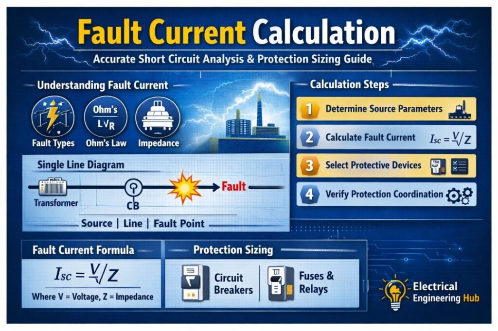
This guide explains what fault current is, the standard fault current formula, different calculation methods, important terminology, and practical examples used in industrial and commercial electrical systems.
What Is Fault Current?
Fault current is the abnormal current that flows when an unintended low-impedance path develops between energized conductors or between a conductor and ground.
Unlike the normal load current, fault current is limited mainly by the impedance of the electrical system. Lower system impedance produces higher fault current, while higher impedance reduces the fault magnitude.
Common causes include:
- Damaged cable insulation
- Equipment failure
- Water ingress
- Mechanical damage
- Loose electrical connections
- Lightning strikes
- Human error during maintenance
The objective of Fault Current Calculation is to determine the maximum and minimum fault current that may occur at a specific location in the electrical network.
Why Fault Current Calculation Is Important
Every protective device is designed to interrupt a limited amount of fault current. If the available fault current exceeds the interrupting capacity of a breaker, catastrophic failure may occur.
Proper Fault Current Calculation helps engineers:
| Benefit | Purpose |
|---|---|
| Select circuit breakers | Ensure interrupting capacity is sufficient |
| Size protective relays | Improve fault detection accuracy |
| Verify cable withstand ratings | Prevent thermal damage |
| Design busbar systems | Check electromechanical forces |
| Coordinate protection | Minimize unnecessary outages |
| Improve personnel safety | Reduce arc flash hazards |
Accurate calculations also support compliance with IEC 60909, IEEE 551 (Violet Book), IEEE 242 (Buff Book), NEC, and utility design practices.
Types of Fault Current Terminology
Many engineers use several related terms interchangeably, although they have different meanings. Understanding these definitions improves communication during system design and protection studies.
| Term | Meaning |
|---|---|
| Fault current | General term for abnormal current during any electrical fault |
| Short circuit current | Current flowing during a phase-to-phase or phase-to-ground short circuit |
| Available fault current | Maximum current available from the power source at a specific location |
| Prospective fault current | Theoretical current before protective devices begin limiting it |
| Fault level | System fault capacity, usually expressed in kA or MVA |
| Fault duty | Maximum current that equipment must safely withstand or interrupt |
In most practical applications, fault current and short circuit current refer to the same phenomenon, but available fault current specifically represents the current supplied by the electrical source before any current-limiting action occurs.
Types of Electrical Faults
Different fault types produce different current levels because the fault path impedance changes.
| Fault Type | Description | Typical Severity |
|---|---|---|
| Three-phase fault | All three phases short together | Highest current |
| Line-to-line fault | Two phases short together | High current |
| Double line-to-ground fault | Two phases connected to ground | Medium to high |
| Single line-to-ground fault | One phase touches ground | Most common |
| Open conductor fault | Broken conductor | Low fault current |
Three-phase faults generally produce the maximum fault current and are commonly used when selecting interrupting ratings for switchgear.
Fault Current Formula
The basic fault current formula is based on Ohm’s Law.
Single-Phase Formula
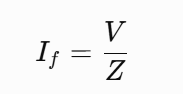
Where:
| Symbol | Meaning |
|---|---|
| If | Fault current (A) |
| V | System voltage (V) |
| Z | Total system impedance (Ω) |
This equation assumes that the total impedance includes transformer impedance, cable impedance, generator impedance, and source impedance.
Three-Phase Fault Current Formula
For balanced three-phase systems:
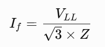
Where:
- VLL = Line-to-line voltage
- Z = Total positive sequence impedance
This is the most common fault current equation used in industrial power system studies.
How to Calculate Fault Current
The calculation process follows a logical sequence regardless of system size.
Step 1: Identify the Fault Location
Choose the exact bus, panel, MCC, switchboard, or equipment where the fault analysis is required.
Step 2: Determine the Source Voltage
Record the nominal system voltage such as:
- 230 V
- 400 V
- 415 V
- 480 V
- 690 V
- 11 kV
- 33 kV
Step 3: Calculate Total System Impedance
Include all significant impedance between the source and the fault point:
- Utility source impedance
- Transformer impedance
- Generator impedance
- Cable impedance
- Bus duct impedance
- Reactor impedance
Step 4: Apply the Fault Current Formula
Insert the values into the appropriate equation for single-phase or three-phase systems.
Step 5: Verify Equipment Ratings
Compare the calculated value with:
- Circuit breaker interrupting rating
- Switchgear short-time withstand rating
- Busbar withstand current
- Protective relay settings
Fault Current Calculation Example
Consider a 415 V three-phase system with a total impedance of 0.025 Ω.
Using the three-phase equation:
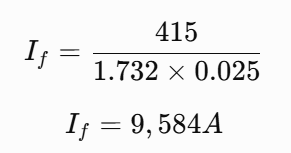
The calculated fault current is approximately:
9.58 kA
This means every protective device installed at that location should safely interrupt at least this level of current, preferably with an adequate safety margin.
Designing busbar protection? Use our Busbar Protection Calculator right here.
Factors Affecting Fault Current
Several variables influence the final calculated value.
| Factor | Effect on Fault Current |
|---|---|
| Transformer size | Larger transformers increase fault current |
| Transformer impedance | Higher impedance reduces fault current |
| Cable length | Longer cables reduce fault current |
| Cable size | Larger conductors increase fault current |
| Utility network strength | Stronger utility systems increase available current |
| Generator contribution | Increases short circuit current |
| Reactors | Limit fault current |
| Motor contribution | Adds current during initial fault cycles |
These factors should always be included in professional short circuit studies.
Fault Current Calculation Using Transformer Data
Transformer impedance has a significant effect on fault current.
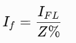
The approximate secondary fault current can be estimated using:
Where:
- IFL = Full-load current
- Z% = Transformer percentage impedance expressed as a decimal
Example:
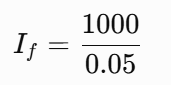
A transformer delivers 1,000 A full-load current with 5% impedance.
Fault current:
20,000 A (20 kA)
This simplified method is widely used for preliminary equipment selection. Follow our detailed Guide on transformer fault current calculation here.
Fault Current Calculation Methods
Different projects require different levels of calculation accuracy.
| Method | Application |
|---|---|
| Manual calculation | Small electrical systems |
| Per-unit method | Medium and large power systems |
| IEC 60909 method | International short circuit studies |
| ANSI/IEEE method | North American projects |
| Software analysis | Complex industrial plants |
Software packages can automatically include motors, generators, cables, transformers, and utility contributions while producing detailed reports.
Standards Used for Fault Current Calculation
Several international standards define accepted calculation methods.
| Standard | Purpose |
|---|---|
| IEC 60909 | Short circuit current calculation |
| IEEE 551 | Industrial power system analysis |
| IEEE 242 | Protection coordination |
| IEEE C37 Series | Circuit breaker ratings |
| NEC Article 110 | Available fault current marking |
| IEC 61439 | Switchgear verification |
Following recognized standards improves safety, consistency, and regulatory compliance.
Common Mistakes During Fault Current Calculation
Even experienced engineers can overlook important parameters.
Avoid these common errors:
- Ignoring utility source impedance
- Excluding motor contribution
- Using incorrect transformer impedance
- Neglecting cable impedance
- Mixing phase and line voltage
- Ignoring X/R ratio in detailed studies
- Using outdated utility fault level data
Reviewing assumptions before finalizing calculations helps prevent costly design errors.
Applications of Fault Current Calculation
Fault current studies are essential across almost every electrical installation.
Typical applications include:
- Industrial manufacturing plants
- Commercial buildings
- Data centers
- Solar photovoltaic systems
- Wind farms
- Utility substations
- Oil and gas facilities
- Water treatment plants
- Hospitals
- Mining operations
These studies ensure that equipment remains protected throughout its service life.
Frequently Asked Questions
What is fault current?
Fault current is the abnormal current that flows through an electrical system when a short circuit or ground fault creates a low-resistance path.
How do you calculate fault current?
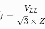
Fault current is calculated by dividing the system voltage by the total impedance between the source and the fault location. Three-phase systems use the equation
What is the difference between fault current and short circuit current?
Fault current is a general term for current during any electrical fault, while short circuit current specifically refers to current caused by a short circuit between conductors or to ground.
Why is fault current calculation necessary?
It helps engineers select correctly rated circuit breakers, relays, busbars, transformers, cables, and switchgear while ensuring safe system operation.
Which standard is commonly used for fault current calculation?
IEC 60909 is widely used internationally, while IEEE 551 and related ANSI/IEEE standards are commonly applied in North America.
Conclusion
Fault Current Calculation forms the foundation of safe electrical system design. Whether you are designing a small commercial installation or a large industrial power network, knowing the available fault current ensures that protective devices, switchgear, transformers, and cables can safely withstand and interrupt abnormal conditions.
By understanding the fault current formula, applying the correct calculation method, and considering system impedance, engineers can improve protection coordination, reduce equipment damage, and maintain compliance with recognized standards such as IEC 60909 and IEEE 551. Accurate analysis not only enhances system reliability but also protects personnel and critical electrical assets during fault conditions.
Get new guides in your feed. Follow Electrical Insights on LinkedIn for new electrical standards guides, calculators and design tips from Azad Circuit Hub.
FaultCurrentCalculation, #ShortCircuitAnalysis, #ElectricalEngineering, #PowerSystemProtection, #RelayCoordination, #FaultAnalysis, #ElectricalCalculations, #PowerSystemDesign, #CircuitProtection, #ElectricalSafety
