DC to DC Converter Design: A Comprehensive Guide
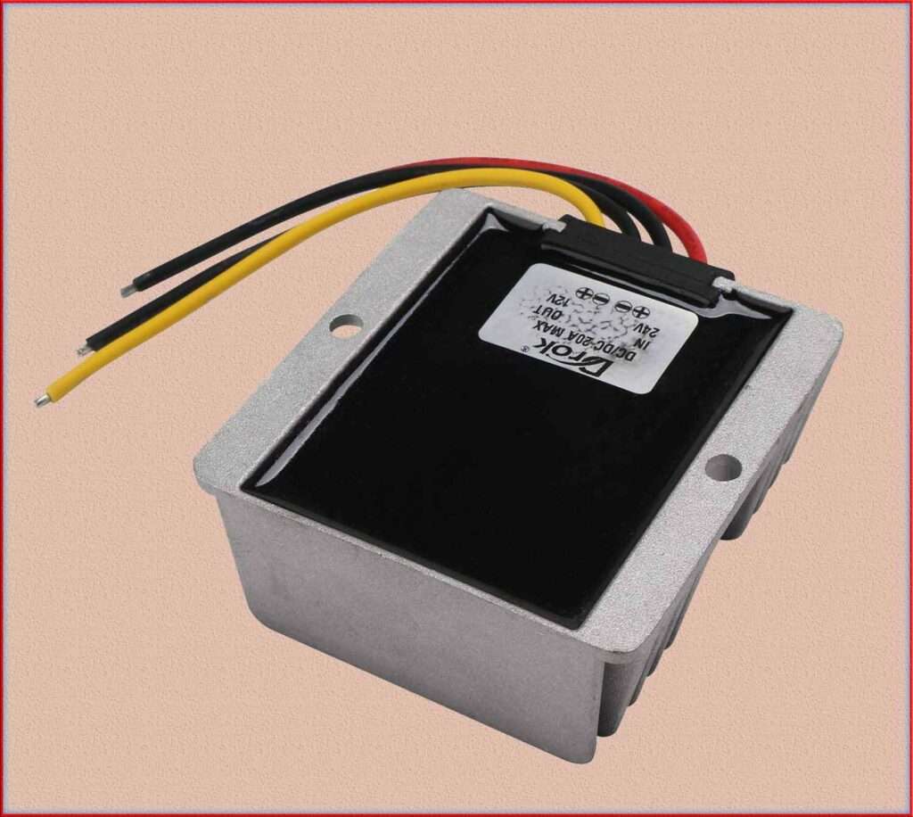
DC to DC converter design involves several steps to ensure the converter’s efficiency, stability, and proper voltage regulation. Let’s go through a step-by-step guide for designing a buck converter, which is one of the most common types of DC to DC converters.
Read More

In this guide, we will use calculations and examples to illustrate each step of the design process.
DC to DC Converter Design
Determine Design Specifications
Define the specifications of the DC to DC converter design, including the input voltage (Vin), output voltage (Vout), maximum output current (Iout), efficiency requirements, and any other specific requirements for your application. For this example, let’s design a buck converter with the following specifications:
Vin = 24V
Vout = 12V
Iout = 5A
Efficiency > 90%
Choose Switching Frequency
Select the switching frequency for the converter. A higher switching frequency generally allows for smaller and more compact components but may introduce more switching losses. For this example, let’s choose a switching frequency of 200 kHz.
Calculate Duty Cycle
The duty cycle (D) of a buck converter is the ratio of the time during which the switch is ON to the total switching period. It can be calculated using the formula:
D = Vout / Vin
In our example: D = 12V / 24V = 0.5
Calculate Inductor Value
The inductor value (L) is crucial for energy storage and ripple current control. It can be calculated using the formula:
L = (Vin – Vout) x (D / (fs x Iout))
Where fs is the switching frequency.
In our example: L = (24V – 12V) x (0.5 / (200,000 Hz x 5A)) ≈ 6.4 μH
Choose Inductor and Capacitor
Select standard inductor and capacitor values that are close to the calculated values. In this case, you might choose a 6.8 μH inductor and a 100 μF output capacitor.
Calculate Output Capacitor
ESR The equivalent series resistance (ESR) of the output capacitor affects the converter’s output ripple voltage. Calculate the output capacitor ESR using the formula:
ESR = (Vout x ΔIout) / (ΔVout x Iout)
Where ΔIout is the output current ripple and ΔVout is the output voltage ripple.
Choose MOSFET and Diode
Select appropriate MOSFET and diode components based on the input voltage, output current, and switching frequency. Ensure that they can handle the required voltage and current ratings.
Design Control Circuitry
Design the control circuitry, which may include a pulse-width modulation (PWM) controller, feedback circuit, and voltage regulation loop, to regulate the output voltage.
Simulate and Prototype
Simulate the DC to DC converter design using software tools like LTspice or MATLAB to verify its performance. Build a prototype and test it to validate the design’s efficiency and stability.
Optimize and Fine-Tune
Based on simulation and testing results, fine-tune the design to meet efficiency and performance goals. Consider factors like component losses, transient response, and thermal management during the optimization process.
In conclusion, DC to DC converter design involves several steps, including determining design specifications, calculating duty cycle, inductor value, and output capacitor ESR, choosing suitable components, designing control circuitry, simulating and prototyping, and optimizing the design.
Following this step-by-step guide and performing necessary calculations and simulations will help you create an efficient and reliable DC to DC converter for your specific application.
Related Posts:
- A Quick Guide to Oscillator Circuit Diagram and Working
- Dc to Dc Converter: Important Things to know in your first Converter
- AC to DC Converter: Everything You need to Know
- How to Choose the Right Type of HIGH PASS FILTER!
- How To Make Your Product Stand Out With LOW PASS FILTER?
- Schmitt Trigger: Important Types, Working & Applications
Subscribe to our Newsletter “Electrical Insights Daily” to get the latest updates in Electrical Engineering. You can also Follow us LinkedIn and Facebook to see our latest posts on Electrical Engineering Topics.
