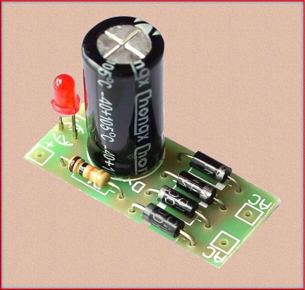
AC to DC Converter Design: A Comprehensive Guide
AC to DC converter design involves transforming the alternating current (AC) from the power mains into a direct current (DC) with a specific output voltage. In this step-by-step guide, we will focus on designing a full-wave bridge rectifier followed by a capacitor filter to convert AC to a stable DC voltage.
Read More

Let’s go through each step of the design process, including calculations and an example.
AC to DC Converter Design
Determine Design Specifications
Define the specifications of the AC to DC converter design, including the input voltage (Vin), desired output voltage (Vout), output current (Iout), and any specific requirements for your application. For this example, let’s proceed to an AC to DC converter design with the following specifications:
Vin = 120V (rms) at 60Hz
Vout = 12V DC
Iout = 1A
Choose Rectifier Configuration
Select the rectifier configuration based on the desired output voltage and current. For this guide, we will use a full-wave bridge rectifier, which provides a more stable and efficient output compared to a half-wave rectifier.
Calculate Peak Output Voltage
The peak output voltage of the full-wave bridge rectifier can be calculated as follows:
Vp = Vin x √2
In our example:
Vp = 120V x √2 ≈ 169.71V
Select Diodes
Choose diodes that can handle the peak voltage and current requirements. Ensure that the diodes have a sufficient reverse voltage rating and forward current rating.
Design the Capacitor Filter
The capacitor filter smooths out the rectified voltage to produce a more stable DC output. The capacitance required can be calculated using the following formula:
C = Iout / (2 x π x f x Vripple)
Where “f” is the AC frequency (60Hz in this example) and Vripple is the allowable output voltage ripple.
Let’s assume an allowable output voltage ripple of 1% of the output voltage:
Vripple = 0.01 * Vout = 0.01 * 12V = 0.12V
C = 1A / (2 * π * 60Hz * 0.12V) ≈ 2200μF
Choose a standard capacitor value close to the calculated value, such as 2200μF or 2200uF.
Select Filter Capacitor
Voltage Rating Ensure that the selected capacitor has a voltage rating higher than the peak rectified voltage. In our example, choose a capacitor with a voltage rating higher than 169.71V.
Design the Load Resistor
To ensure proper filtering, add a load resistor across the output terminals. The load resistor should be smaller than the minimum load current requirement of the capacitor. For this example, let’s choose a load resistor of 10Ω.
Simulate and Prototype
Simulate the AC to DC converter design using software tools like LTspice or MATLAB to verify its performance. Build a prototype and test it to validate the design’s efficiency and stability.
Optimize and Fine-Tune
Based on simulation and testing results, fine-tune the design to meet efficiency and performance goals. Consider factors like component losses, output voltage regulation, and thermal management during the optimization process.
Safety Considerations
Ensure that the AC to DC converter design complies with safety standards and regulations. Implement safety features like fuses and appropriate grounding to protect against overcurrent and electric shock hazards.
In conclusion, AC to DC converter design involves transforming the AC input from the power mains into a stable DC output voltage. This step-by-step guide focused on designing a full-wave bridge rectifier followed by a capacitor filter. It included calculations for peak output voltage, capacitor value, and load resistor, as well as the selection of suitable components like diodes and capacitors.
Through simulation, prototyping, and optimization, you can create an efficient and reliable AC to DC converter suitable for your specific application. Always prioritize safety considerations to ensure the converter operates safely and reliably.
Subscribe to our Newsletter “Electrical Insights Daily” to get the latest updates in Electrical Engineering. You can also Follow us LinkedIn and Facebook to see our latest posts on Electrical Engineering Topics.
