A4988 Pinout: A Comprehensive Guide
Discover the functionality and versatility of the Stepper Motor Driver Module A4988 Pinout, a crucial component in the world of robotics and automation. Let’s delve into the key details, with a specific focus on the A4988 pinout for a clearer understanding.

Read More About
Stepper Motor Driver Module A4988
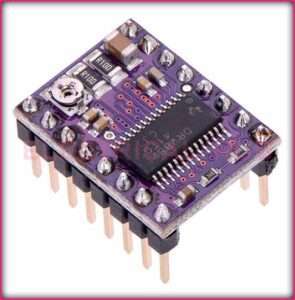
The A4988 is a stepper motor driver module that plays a pivotal role in controlling the precise movements of stepper motors. Whether you’re working on a 3D printer, CNC machine, or any other project requiring accurate motor control, the A4988 is a go-to choice.
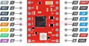
A4988 Pinout Configuration
Understanding the A4988 pinout configuration is essential for effectively integrating the A4988 into your projects. Here’s a breakdown of the key pins:
MS1, MS2, MS3 (Microstep Resolution): These pins determine the microstep resolution, allowing you to set the stepping mode for the stepper motor. Configuring these pins enables fine-tuning of motor movement.
VMOT (Motor Power Supply Voltage): Connect this pin to the motor power supply voltage (typically 8V to 35V) to ensure the proper functioning of the stepper motor.
GND (Ground): Establish the ground connection by linking this pin to the ground of your power supply or microcontroller.
VDD (Logic Power Supply Voltage): Provide the logic power supply voltage (typically 3V to 5.5V) to this pin to power the internal logic circuitry of the A4988.
DIR (Direction Input): Control the direction of the stepper motor by connecting this pin to a digital output on your microcontroller.
STEP (Step Input): Trigger individual steps of the stepper motor by connecting this pin to another digital output on your microcontroller.
RESET (Reset Input): This pin resets the internal translator circuit, and it is optional to use.
SLEEP (Sleep Input): Putting the A4988 into sleep mode is achieved by connecting this pin to a digital high signal.
ENABLE (Enable Input): Enable or disable the motor outputs by connecting this pin to a digital high or low signal, respectively.
VREF (Reference Voltage): Adjust the motor current by connecting this pin to a potentiometer, allowing precise control over the motor’s power.

Understanding the A4988 pinout is crucial for configuring the module to suit the requirements of your stepper motor and project. Whether you’re a seasoned engineer or a hobbyist, the A4988 provides a reliable and efficient solution for precise stepper motor control in various applications.
Frequently Asked Questions
What is the A4988?
The A4988 is a microstepping stepper motor driver widely used for controlling the movement of stepper motors in various applications, such as 3D printers, CNC machines, and robotics.
How many pins does the A4988 have?
The A4988 typically has 16 pins, including power supply, logic input, motor output, and configuration pins.
What are the main power supply pins on the A4988?
The main power supply pins are VMOT (motor power supply voltage) and GND (ground).
What is the purpose of the logic supply pins on the A4988?
The logic supply pins, VDD and GND, provide power to the internal logic circuitry of the A4988.
How are the motor coils connected to the A4988?
The motor coils are connected to the A1, A2, B1, and B2 pins on the A4988.
What is the purpose of the DIR and STEP pins on the A4988?
The DIR (Direction) pin controls the direction of the motor rotation, while the STEP pin generates pulses to drive the motor one step at a time.
How can microstepping be configured on the A4988?
Microstepping can be configured using the MS1, MS2, and MS3 pins. The combination of high or low states on these pins determines the microstepping resolution.
What does the ENABLE pin do on the A4988?
The ENABLE pin enables or disables the motor outputs. When pulled low, the motor is enabled, and when pulled high, the motor is disabled.
How is the current limit set on the A4988?
The current limit is set by adjusting the voltage on the VREF pin. The relationship between VREF, current, and sense resistor value is used to determine the current limit.
Is there a specific wiring sequence for the motor coils on the A4988?
The wiring sequence for the motor coils is typically A1-A2-B1-B2 or B1-B2-A1-A2, depending on the desired direction of rotation.
What is the purpose of the SLEEP and RESET pins on the A4988?
The SLEEP pin, when pulled low, puts the A4988 into a low-power sleep mode. The RESET pin resets the internal translator circuit and is optional for use.
Can the A4988 drive multiple stepper motors simultaneously?
While it’s possible to drive multiple stepper motors using separate A4988 drivers, each A4988 is typically dedicated to a single motor.
Are there specific safety considerations when using the A4988?
Ensure proper heatsinking and cooling to prevent overheating. Additionally, avoid exceeding the maximum specified current for the motor.
Worth Read Posts
Subscribe to our Newsletter “Electrical Insights Daily” to get the latest updates in Electrical Engineering. You can also Follow us on LinkedIn and Facebook to see our latest posts on Electrical Engineering Topics.

