DRV8825 Stepper Motor Driver: A Comprehensive Guide
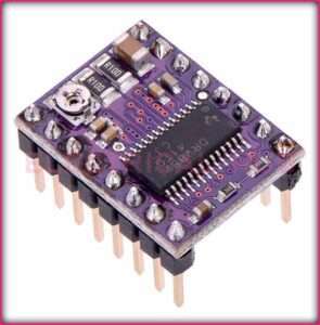
The DRV8825 stepper motor driver, a technological marvel crafted by Texas Instruments, stands as a pinnacle in the realm of bipolar stepper motor control. Tailored for applications demanding meticulous motor management, this compact driver has found its place in diverse fields such as 3D printing, CNC machining, robotics, and beyond.
Read More About

Key Features of DRV8825 Stepper Motor Driver
Microstepping Mastery:
The DRV8825 boasts unparalleled microstepping capabilities, offering resolutions including full-step, half-step, 1/4-step, 1/8-step, 1/16-step, and an impressive 1/32-step. This enables silky-smooth motion and heightened precision.
Current Control Wizardry:
Setting the motor current becomes an art with the DRV8825. Equipped with an adjustable current control feature, users can tailor the current flow through the motor windings to meet the specific demands of their stepper motor. A simple twist of the onboard potentiometer accomplishes this feat.
Voltage Versatility:
Operating seamlessly across a wide voltage range, typically 8.2V to 45V, the DRV8825 exhibits adaptability, making it a versatile choice for applications with varied power supply configurations.
Guardian of Motors: Protection Features:
This driver is no stranger to safeguarding both itself and the connected components. With thermal shutdown protection, it prevents overheating by disabling outputs when the temperature surpasses a predefined threshold. Overcurrent protection ensures the current stays within safe limits, shielding against potential damage.
Chopper Drive Elegance:
The DRV8825 employs a sophisticated chopper drive technique to regulate current flow through motor windings. This not only optimizes power consumption but also minimizes heat generation, ensuring efficient and effective motor control.
Seamless Integration: Step and Direction Interface:
Communicating effortlessly with external controllers or microcontrollers through a step and-direction interface, the DRV8825 simplifies integration with various control systems. Its compatibility spans a wide range of microcontrollers, making it a seamless fit for diverse applications.
Cool and Compact: Integrated Heat Sink:
Embracing a compact form factor, the DRV8825 features an integrated heat sink that aids in efficient heat dissipation. This not only preserves the driver’s reliability but also ensures optimal performance during extended operations.
Technical Specifications of DRV8825 Stepper Motor Driver
- Input Voltage Range: 8.2V to 45V
- Microstepping Resolutions: Full-step, half-step, 1/4-step, 1/8-step, 1/16-step, 1/32-step
- Current Control: Adjustable via onboard potentiometer
- Protection Features: Thermal shutdown, overcurrent protection
- Chopper Drive Technique: Implemented for precise current regulation
- Heat Dissipation: Integrated heat sink for efficient temperature management
- Size: Compact design for space-conscious applications
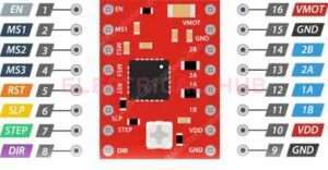
DRV8825 Stepper Motor Driver pinout

Here’s the pinout of the DRV8825 Stepper Motor Driver:
VMOT: Motor Power Supply (Connect to the positive side of the motor power supply, typically 8V to 35V).
GND: Ground (Connect to the ground of the motor power supply).
VDD: 5V Logic Power (Connect to a 5V power source for the internal logic of the DRV8825).
DIR: Direction Control (Connect to a digital output pin on your microcontroller to control the motor direction).
STEP: Step Control (Connect to a digital output pin on your microcontroller to generate step pulses for the motor).
MODE0, MODE1, MODE2: Microstepping Mode Selection (Connect to GND or VDD to set microstepping mode).
RESET: Reset (Optional – Reset internal translator logic, often left unconnected).
SLEEP: Sleep Mode (Optional – Puts DRV8825 into low-power sleep mode when pulled LOW, often left unconnected).
FAULT: Fault Output (Goes LOW in case of a fault condition, such as overtemperature or overcurrent).
REFA, REFB: Current Limit Reference (Connect to a resistor network to set the motor current limit).
MS1, MS2, MS3: Microstepping Mode Selection (Connect to GND or VDD to set microstepping mode).
EN (Enable): Enable Motor Outputs (Connect to a digital output pin on your microcontroller to enable/disable motor outputs).
Please note that the RESET and SLEEP pins are optional and are often left unconnected in typical usage. The specific functions of these pins may vary based on the application and module version.
DRV8825 Stepper Motor Driver Arduino
To use the DRV8825 stepper motor driver with an Arduino, you’ll need to follow these general steps. This example assumes a simple setup with one stepper motor. Be sure to consult the datasheet of your specific stepper motor and the DRV8825 module for accurate specifications.
Wiring Connections:
Connect the motor to the DRV8825 module. The stepper motor should be connected to the A1, A2, B1, and B2 terminals on the DRV8825.
Connect the DRV8825 to the Arduino:
- Connect VMOT and GND on the DRV8825 to an external power supply matching your stepper motor’s voltage requirements.
- Connect the GND and +5V pins on the DRV8825 to GND and 5V on the Arduino for logic power.
- Connect the STEP and DIR pins on the DRV8825 to digital output pins on the Arduino.
- Optionally, connect the MS1, MS2, and MS3 pins on the DRV8825 to digital output pins on the Arduino if you want to set microstepping modes. You can also leave them unconnected for full-step operation.
- Connect the EN (Enable) pin to a digital output pin on the Arduino if you want to disable the motor when it’s not in use.
Arduino Code DRV8825 Stepper Motor Driver:

Now, you can use a simple Arduino sketch to control the stepper motor. Below is an example using the AccelStepper library:
#include <AccelStepper.h>

// Define stepper motor connections and create a stepper object

#define STEP_PIN 2

#define DIR_PIN 3

AccelStepper stepper(1, STEP_PIN, DIR_PIN);

void setup() {

  // Set the maximum speed and acceleration

  stepper.setMaxSpeed(1000);

  stepper.setAcceleration(500);

}

void loop() {

  // Move the stepper motor one full revolution

  stepper.moveTo(200);

  stepper.run();

}
Adjustments:
- Adjust the values in the code according to your specific requirements, such as the maximum speed, acceleration, and target position.
- Use a multimeter to measure the current across the sense resistor (VREF) and adjust it if necessary to match the current requirements of your stepper motor.
Important Notes:
- Always power off your system before making any wiring adjustments.
- Ensure that the power supply voltage matches the specifications of your stepper motor.
- Refer to the datasheets of the DRV8825 module, the AccelStepper library, and your stepper motor for detailed specifications and guidelines.
drv8825 vs a4988
Here’s a simple table summarizing the differences between the DRV8825 and A4988 stepper motor drivers:
| Feature | DRV8825 | A4988 |
| Microstepping | 1, 1/2, 1/4, 1/8, 1/16, 1/32 | 1, 1/2, 1/4, 1/8 |
| Current Control | Potentiometer | Potentiometer |
| Maximum Current | Up to 2.5 A per phase | Typically 1-2 A per phase |
| Voltage Regulation | Yes | Yes |
| Over-Temperature Protection | Yes | No |
| Cost | Slightly more expensive | Generally less expensive |
| Heat Dissipation | Requires heatsink | May require heatsink |
| Pin Compatibility | Different pinout | Compatible with StepStick and Pololu A4988 boards |
DRV8825 Stepper Motor Driver vref
The VREF (Reference Voltage) on a DRV8825 stepper motor driver is a critical parameter that determines the current supplied to the stepper motor windings. Adjusting the VREF allows you to set the current limit, which is crucial for preventing overheating and damage to both the driver and the motor.
Here’s how you can calculate and set the VREF on a DRV8825:
Determine the Desired Current:
Know the current rating of your stepper motor. This information is typically specified by the manufacturer.
Use the Formula:
The formula to calculate VREF is:
VREF = I_RMS x 8 x R_sense
- VREF is the voltage you want to set.
- I_RMS is the desired current in amps.
- R_sense is the sense resistor value on the DRV8825 module. The common value is 0.1 ohms.
Example Calculation:
If you have a stepper motor with a 2A current rating and a sense resistor of 0.1 ohms, the VREF would be:
VREF = 2A x 8 x 0.1 ohms = 1.6V
Adjust the Potentiometer:
- Locate the potentiometer on the DRV8825 module.
- Use a non-conductive screwdriver to turn the potentiometer and set the VREF to the calculated value.
Measure VREF:
You can use a multimeter to measure the voltage across the potentiometer or between the GND and the potentiometer’s wiper.
Verify with Datasheet:
Refer to the datasheet of your specific DRV8825 module for any additional guidelines or information regarding VREF adjustment.
Important Considerations:
- Be careful not to exceed the maximum current rating of your stepper motor or the DRV8825.
- Setting the current too high can lead to overheating, so ensure that you are within the safe operating limits of your motor and driver.
- Always power off your system before adjusting VREF to avoid electric shock or damage to components.
dRV8825 microstepping table
The DRV8825 stepper motor driver supports different microstepping resolutions, allowing for finer control and smoother motion. Here’s a table illustrating the microstepping options and corresponding control pin configurations for the DRV8825:
| MS1 Pin | MS2 Pin | MS3 Pin | Microstepping Resolution | Control Pins Configuration |
| Low | Low | Low | Full step | DIR: X, STEP: X, ENABLE: X |
| High | Low | Low | Half step | DIR: X, STEP: X, ENABLE: X |
| Low | High | Low | 1/4 step | DIR: X, STEP: X, ENABLE: X |
| High | High | Low | 1/8 step | DIR: X, STEP: X, ENABLE: X |
| Low | Low | High | 1/16 step | DIR: X, STEP: X, ENABLE: X |
| High | Low | High | 1/32 step | DIR: X, STEP: X, ENABLE: X |
| Low | High | High | Reserved | DIR: X, STEP: X, ENABLE: X |
| High | High | High | Reserved | DIR: X, STEP: X, ENABLE: X |
- “Low” means the corresponding pin is connected to the ground (GND).
- “High” means the corresponding pin is connected to the logic high voltage (VDD or 5V).
- “X” represents the state of the pin, which might be connected to a microcontroller output.
For the control pins configuration:
- DIR (Direction) Pin: Connect to a digital output pin on your microcontroller (DIR: X).
- STEP Pin: Connect to another digital output pin on your microcontroller (STEP: X).
- ENABLE (EN) Pin: Connect to a digital output pin on your microcontroller (ENABLE: X).
For example, if you want to set the microstepping to 1/8 step resolution, you would set the MS1, MS2, and MS3 pins to High, Low, and Low, respectively (1 1 0).
Remember to configure the microstepping resolution according to your specific application and the desired balance between motor smoothness and torque. Additionally, make sure to set the pins before powering up the DRV8825 to ensure proper configuration.
Applications of DRV8825 Stepper Motor Driver
The DRV8825 stepper motor driver is widely used in various applications where precise control of stepper motors is required. Some common applications include:
3D Printers:
DRV8825 drivers are commonly used in 3D printers to control the movement of stepper motors responsible for moving the printer’s axes and extruders with high precision.
CNC Machines:
CNC (Computer Numerical Control) machines utilize stepper motors for precise control of tool movement. DRV8825 drivers help in controlling the motion of these motors in CNC applications.
Robotics:
Stepper motors, coupled with DRV8825 drivers, are frequently used in robotics for controlling various robotic joints and movements with accuracy and reliability.
Automated Systems:
In automated systems, such as conveyor belts, sorting machines, or packaging equipment, DRV8825 drivers can be employed to control the movement of motors with precise positioning.
Camera Stabilization Systems:
Gimbal systems in camera stabilization equipment often use stepper motors and drivers like the DRV8825 to ensure smooth and stable camera movement.
Telescope Mounts:
Stepper motors controlled by DRV8825 drivers find applications in telescope mounts, allowing for precise adjustments and tracking of celestial objects.
Laboratory Equipment:
Scientific instruments and laboratory equipment may use stepper motors and drivers to control various mechanisms, such as sample handling or measurement devices.
DIY Projects:
DRV8825 drivers are popular in various DIY projects where precise motor control is required. This includes hobbyist projects, small automation setups, and educational projects.
Automotive Systems:
In automotive applications, stepper motors are employed in systems such as automotive gauges, HVAC controls, and headlamp leveling systems, where precise and controlled movements are necessary.
Prototyping and Development:
Engineers and hobbyists use DRV8825 drivers during the prototyping and development phase of projects to test and implement motion control systems before transitioning to a final design.
Electronic Components Testing:
Stepper motors controlled by DRV8825 drivers can be used in testing equipment for electronic components, where precise movements are required for testing purposes.
Linear Motion Systems:
DRV8825 drivers can be used in linear motion systems for tasks such as precision positioning in manufacturing or laboratory automation.
Frequently Asked Questions
What is the DRV8825 Stepper Motor Driver used for?
The DRV8825 is a stepper motor driver that is commonly used to control bipolar stepper motors in various applications, such as 3D printers, CNC machines, robotics, and other projects requiring precise motor control.
How does the DRV8825 work?
The DRV8825 uses a chopper microstepping technique to control the current and position of a bipolar stepper motor. It interprets step and direction signals from a microcontroller and adjusts the motor windings’ current to move the motor in the desired direction and distance.
What is the maximum current the DRV8825 can handle?
The DRV8825 can handle a maximum current of 2.5A per phase. The current can be adjusted using the onboard potentiometer.
What is microstepping, and does the DRV8825 support it?
Microstepping is a technique that divides each full step of a stepper motor into smaller steps, providing smoother motion and increased resolution. The DRV8825 supports microstepping up to 1/32 steps.
How do I set the current on the DRV8825?
The current can be set by adjusting the potentiometer on the DRV8825. The formula to calculate the reference voltage (VREF) is VREF = I_trip_max * Rsense, where I_trip_max is the desired maximum current and Rsense is the sense resistor value (0.1 ohms on the DRV8825).
Can the DRV8825 drive both low-impedance and high-impedance stepper motors?
Yes, the DRV8825 is designed to drive both low-impedance and high-impedance stepper motors effectively.
How do I connect the DRV8825 to a microcontroller?
The DRV8825 typically requires connections for step, direction, enable, and power supply. The step and direction pins are controlled by a microcontroller, and the enable pin can be used to disable the motor. Additionally, power connections for the motor and logic voltage are needed.
What is the difference between the DRV8825 and A4988 stepper motor drivers?
Both the DRV8825 and A4988 are popular stepper motor drivers. The DRV8825 generally offers higher microstepping resolutions (up to 1/32) and can handle higher current (2.5A) compared to the A4988. However, the A4988 is often considered more straightforward for beginners.
Worth Read Posts
Subscribe to our Newsletter “Electrical Insights Daily” to get the latest updates in Electrical Engineering. You can also Follow us on LinkedIn and Facebook to see our latest posts on Electrical Engineering Topics.

