
Demand Factor For Motor Loads: Important Examples
When several motors operate in the same electrical installation, the connected load can be much higher than the load actually required at one time. This is where Demand Factor For Motor Loads becomes useful. It helps engineers estimate the maximum expected operating load instead of simply adding the nameplate ratings of every motor.
A proper demand calculation can reduce unnecessary transformer capacity, feeder size, generator rating, and electrical infrastructure costs while maintaining adequate capacity for starting and continuous operation.
For motor installations, demand factor should not be confused with diversity factor, load factor, or motor efficiency. Each value describes a different part of the electrical load profile.
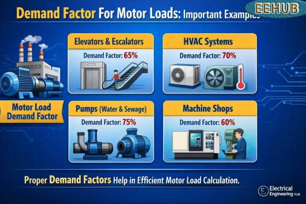
Quick Comparison: Motor Demand Factor at a Glance
| Motor Load Condition | Typical Demand Factor | Connected Load | Estimated Demand |
|---|---|---|---|
| One continuously operating motor | 1.00 | 10 kW | 10 kW |
| Two motors, both normally running | 0.90–1.00 | 20 kW | 18–20 kW |
| Three motors, intermittent operation | 0.70–0.85 | 30 kW | 21–25.5 kW |
| Multiple industrial motors | 0.60–0.85 | 100 kW | 60–85 kW |
| Mixed motor loads | 0.50–0.80 | 150 kW | 75–120 kW |
These ranges are planning examples rather than universal code values. The actual value should come from operating schedules, equipment data, utility requirements, and the applicable electrical standard.
For a broader explanation of how simultaneous operation affects electrical sizing, see our guide to demand factor and diversity factor before finalizing feeder, transformer, or generator capacity.
What Is Demand Factor For Motor Loads?
Demand factor is the ratio between the maximum demand of an installation and its total connected load.
The basic formula is:
Demand Factor = Maximum Demand / Total Connected Load
For example, suppose a workshop has five motors rated at 20 kW each.
Total connected motor load:
5 × 20 = 100 kW
If the highest measured operating demand is 75 kW:
Demand Factor = 75 / 100 = 0.75
Therefore, the demand factor is 0.75, or 75%.
A value of 1.0 means the entire connected load is being demanded at the same time. A value below 1.0 means that not all connected equipment operates simultaneously at its full rated load.
Why Demand Factor Matters for Motor Installations
Motor loads can create significant differences between connected capacity and actual operating demand. A factory may have dozens of motors installed, but only some may operate simultaneously.
For example, a production line could contain:
- Conveyor motors
- Pumps
- Compressors
- Exhaust fans
- Cooling tower motors
- Hydraulic power units
- Material handling equipment
If every motor nameplate rating is simply added together, the resulting figure may overstate normal operating demand.
That does not mean engineers should always reduce equipment ratings. Motors have starting currents, acceleration requirements, process constraints, and continuous-load considerations. The calculated demand must still provide adequate electrical capacity.
Demand factor is particularly useful when evaluating:
- Transformer capacity
- Generator sizing
- Main switchboards
- Distribution feeders
- MCC capacity
- Cable sizing
- Electrical service capacity
- Utility demand
- Power quality
- Energy consumption estimates
Demand Factor Formula for Motor Loads
The standard relationship is:
DF = MD / CL
Where:
- DF = Demand factor
- MD = Maximum demand
- CL = Total connected load
The maximum demand is normally expressed in kW, kVA, amperes, or another consistent unit.
For motor systems, it is often better to work with actual electrical input power rather than simply using motor shaft horsepower. Motor efficiency and power factor affect the electrical demand.
For example, a 25 hp motor does not draw exactly 25 × 0.746 kW from the supply.
Its approximate mechanical output is:
25 × 0.746 = 18.65 kW
If motor efficiency is 90%:
Electrical input ≈ 18.65 / 0.90 = 20.72 kW
If the power factor is 0.85:
kVA ≈ 20.72 / 0.85 = 24.38 kVA
This distinction becomes important when sizing transformers, generators, and other equipment based on apparent power.
Example 1: Three 10 HP Motors
Consider a small industrial workshop with three 10 hp motors.
Each motor has approximately:
10 × 0.746 = 7.46 kW mechanical output
Assume 90% efficiency.
Electrical input per motor:
7.46 / 0.90 = 8.29 kW
Total connected electrical motor load:
8.29 × 3 = 24.87 kW
Suppose only two motors normally operate simultaneously at full load.
Maximum operating demand:
8.29 × 2 = 16.58 kW
Therefore:
Demand Factor = 16.58 / 24.87
Demand Factor ≈ 0.67
This example shows why connected motor capacity should not automatically be treated as the normal maximum demand.
Example 2: Five 20 HP Motors
Now consider five 20 hp motors installed in a manufacturing facility.
Assume:
- Motor rating = 20 hp
- Quantity = 5
- Efficiency = 92%
- Power factor = 0.88
Mechanical output of one motor:
20 × 0.746 = 14.92 kW
Approximate electrical input:
14.92 / 0.92 = 16.22 kW
Total connected input:
16.22 × 5 = 81.10 kW
If four motors operate simultaneously:
Maximum demand ≈ 16.22 × 4 = 64.88 kW
Demand Factor For Motor Loads:
64.88 / 81.10 = 0.80
So the estimated demand factor is approximately 0.80.
For transformer calculations, apparent power can also be considered:
64.88 / 0.88 ≈ 73.73 kVA
The actual transformer selection would need additional allowances for starting current, future expansion, harmonics, ambient conditions, and applicable design requirements.
Example 3: Pump Station With Different Motor Sizes
A pump station may contain motors with different ratings rather than identical units.
| Motor | Rating | Approx. Input at 90% Efficiency |
|---|---|---|
| Pump 1 | 30 hp | 24.87 kW |
| Pump 2 | 20 hp | 16.59 kW |
| Pump 3 | 15 hp | 12.44 kW |
| Pump 4 | 10 hp | 8.29 kW |
| Pump 5 | 5 hp | 4.15 kW |
| Total | 80 hp | 66.34 kW |
Assume the operating sequence allows Pump 1, Pump 2, and Pump 4 to operate together.
Maximum demand:
24.87 + 16.59 + 8.29 = 49.75 kW
Demand Factor:
49.75 / 66.34 ≈ 0.75
The result is approximately 0.75.
This approach provides a more realistic picture of the installation than simply using the total horsepower.
Example 4: Motor Load With Actual Electrical Rates
Electrical demand is also important because many commercial and industrial electricity tariffs include demand-related charges.
Suppose an industrial facility has a measured monthly peak demand of 250 kW and the applicable demand charge is $12 per kW-month.
Monthly demand charge:
250 × $12 = $3,000
If better scheduling reduces the peak to 210 kW:
210 × $12 = $2,520
Potential monthly saving:
$3,000 − $2,520 = $480
Annualized saving:
$480 × 12 = $5,760
The actual tariff varies by utility, customer class, location, billing period, and tariff structure. Therefore, the $12/kW figure is an illustrative rate, not a universal electricity price.
For a real project, use the latest tariff from the applicable utility instead of relying on a generic rate.
Demand Factor vs Diversity Factor
These two terms are often mixed together, but they are not identical.
Demand factor compares maximum demand with connected load.
Diversity factor compares the sum of individual maximum demands with the maximum demand of the complete system.
For example, three motor groups may each reach their own peak at different times. Their individual peaks could add up to 150 kW, while the facility’s actual simultaneous peak is only 120 kW.
Diversity factor:
150 / 120 = 1.25
Demand factor and diversity factor therefore describe different characteristics of an electrical installation.
Use our demand factor and diversity factor guide to understand how both values work together when sizing electrical distribution systems.
Typical Demand Factor Considerations for Motors
There is no single demand factor that applies to every motor installation.
The correct value depends on the process and operating pattern.
Important factors include:
Operating Schedule
If all motors run continuously, the demand factor can approach 1.0.
If motors operate in alternating cycles, the value may be significantly lower.
Motor Loading
A motor’s nameplate rating represents its rated capacity, not necessarily its actual operating load.
A 50 hp motor operating at 60% of its rated mechanical load does not normally consume the same power as a fully loaded 50 hp motor.
Production Process
Industrial processes often determine when motors operate. Pumps may alternate, conveyors may run only during production, and standby motors may remain off except during maintenance or failure.
Standby Equipment
A standby pump should not automatically be treated as a simultaneous operating load if the operating sequence prevents it from running with the duty pump.
Starting Requirements
Demand calculations should not ignore motor starting current.
Large motors can draw several times their normal running current during starting. This can affect generator sizing, transformer selection, voltage drop, and protection coordination.
Demand Factor and Motor Current
For a three-phase motor, approximate full-load current can be calculated using:
I = P / (√3 × V × PF × η)
Where:
- I = Line current
- P = Motor output power in watts
- V = Line-to-line voltage
- PF = Power factor
- η = Efficiency
For a 20 hp, 480 V, three-phase motor with 90% efficiency and 0.85 power factor:
P = 20 × 746 = 14,920 W
I ≈ 14,920 / (1.732 × 480 × 0.85 × 0.90)
I ≈ 23.5 A
Actual motor full-load current should be checked against the manufacturer’s nameplate and the applicable code tables.
How to Choose a Practical Demand Factor
A measured load profile is usually more reliable than a generic assumption.
For an existing plant, review:
- Historical utility demand data
- Power meter records
- Motor operating schedules
- Production schedules
- Motor nameplate ratings
- Actual motor loading
- Standby equipment
- Future expansion plans
- Transformer loading
- Generator operating requirements
For a new facility, engineers may need to use process documentation, equipment schedules, manufacturer’s data, and engineering judgment.
A conservative value should be used where operating conditions are uncertain.
Common Mistakes in Motor Demand Calculations
One common mistake is treating every motor nameplate rating as simultaneous demand.
Another is converting horsepower directly to electrical kW without considering efficiency.
Other errors include:
- Ignoring power factor
- Ignoring standby motors
- Using outdated utility rates
- Ignoring future expansion
- Treating demand factor as diversity factor
- Forgetting motor starting requirements
- Using generic values without checking the operating sequence
- Selecting transformers only from running kW
- Ignoring continuous-load requirements and local electrical codes
A good design separates normal operating demand from starting and emergency conditions.
Practical Motor Demand Factor Reference
| Application | Planning Range | Main Consideration |
|---|---|---|
| Single continuous motor | 0.90–1.00 | High simultaneous operation |
| Small workshop | 0.70–0.90 | Intermittent equipment |
| Pumping system | 0.60–0.85 | Duty/standby sequence |
| Manufacturing plant | 0.60–0.85 | Production schedule |
| HVAC motor group | 0.60–0.90 | Seasonal and staged operation |
| Large mixed industrial system | 0.50–0.80 | Diverse operating cycles |
These ranges are engineering planning examples and should not replace project-specific load studies or requirements from applicable electrical standards.
Final Takeaway
Demand Factor For Motor Loads provides a practical way to estimate how much of an installation’s connected motor capacity is likely to be required at the same time. It is especially valuable for factories, pumping stations, commercial buildings, HVAC systems, and other facilities with multiple motors.
The key is to base the calculation on actual operating conditions rather than relying blindly on a standard percentage. Motor efficiency, power factor, operating schedules, standby equipment, starting requirements, and future expansion can all change the final design.
For an existing facility, measured demand data gives the strongest basis for the calculation. For a new installation, equipment schedules and realistic operating scenarios should be used.
If you are comparing connected load, maximum demand, and simultaneous operation, our detailed guide to demand factor and diversity factor can help you apply both concepts correctly.
Frequently Asked Questions
What is a typical demand factor for motor loads?
A typical planning value can range from about 0.60 to 0.90 for many industrial motor groups, but there is no universal value. A continuously operating motor can have a value close to 1.0, while diverse intermittent loads may have a substantially lower value.
Can demand factor be greater than 1?
No. Demand factor normally cannot exceed 1.0 because maximum demand cannot be greater than the total connected load when both are measured on a consistent basis.
Is demand factor the same as diversity factor?
No. Demand factor compares maximum demand with connected load. Diversity factor compares the sum of individual maximum demands with the maximum demand of the complete system.
Should motor efficiency be included in demand calculations?
Yes, when converting motor mechanical output into electrical input. Motor efficiency affects the actual electrical power required from the supply. Manufacturer nameplate data should be used whenever available.
Does demand factor determine motor breaker size?
No. Demand factor is mainly a load estimation concept. Motor branch-circuit conductors, overload protection, short-circuit protection, disconnects, and breakers must be selected according to the applicable electrical code, motor data, starting characteristics, and installation conditions.
Get new guides in your feed. Follow Electrical Insights on LinkedIn for new electrical standards guides, calculators and design tips from Azad Circuit Hub.
DemandFactor, #MotorLoads, #ElectricalEngineering, #MotorLoadCalculation, #ElectricalLoad, #DemandFactorCalculation, #MotorSizing, #ElectricalDesign, #NEC, #PowerSystemDesign
