How to Choose the Right Type of HIGH PASS FILTER!
The high pass filter works in a way that permits high frequencies to pass through the filter while blocking lower ones. It’s useful in several applications, like wireless communication systems and audio applications such as equalizers and subwoofers. In fact, it’s one of the easiest filters to make by hand, with only one component involved – the resistor.
Read More About
With your own hands-on experience with this component and its filter function, you can learn the basics of how these devices work so that you can build your own filter if you want to experiment with one in your home or classroom.
What is a high-pass filter circuit?
In our previous article, we discussed low-pass filters in detail. We derive the cut-off frequency formulas and with an example, we elaborated that how the low pass RC filter stops the high-frequency signals. So, now here in this article, we will cover the high pass filter circuit and its working in detail.
When we look at the name of the filter it suggests that it will block the Low-frequency components in the signal and it will let pass the higher-frequency components. The threshold will be decided and calculated by the formula just like in our previous article on the RC low pass filter.
Passive High Pass Filter
We also call this high pass filter a passive high pass because it doesn’t require any external power and is made up of passive elements. There is no amplifying of the signal applied at the input. So, now the main components of the filter are the same as we used in the RC Low pass filters. The arrangement of their connection will change here. The circuit contains the main components resistor “R” and capacitor “C” but in a different orientation.
Let’s have a look at the circuit in the image below.
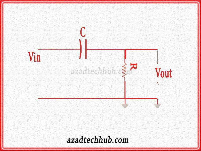
As we can see in the figure that the circuit is almost the same as the RC low-pass filter circuit but the configuration here is different. We can see that we apply the input signal through the capacitor which gets filtered on the initial phase then the output we get across the resistor. This output is just high-frequency signals as the filter blocks the low-frequency signals.
High Pass Filters Working
When we apply the signal at the input, the capacitor behaves like an open circuit towards the signal if its frequency is low. This happens due to the fact that the reactance of the capacitor becomes so high that it doesn’t allow the signal to pass. Therefore, in this way, it acts like an open circuit in RC high-pass filters. This scenario exists until the cut-off frequency or corner frequency. The band until the corner frequency, we name it to stop band.
The reverse happens when we apply high-frequency signals to the input. The capacitor behaves like a short circuit because the reactance “Xc” of the capacitor drops too low that it behaves like a short circuit. Not ideally but nearly close to the short circuit.
Frequency against Gain of high pass filter
As we draw the frequency against gain let’s have a look at the below figure.
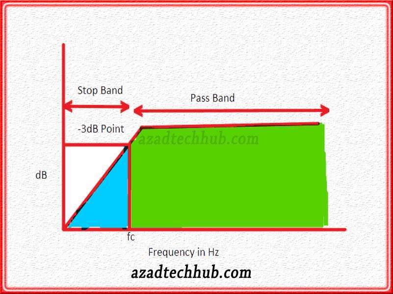
So, from the above circuit, we can clearly see that until cut off or corner frequency the RC high pass filter doesn’t allow the input signals to pass through. The band is called the stop band. But as the frequency get higher than the cut-off or corner frequency, the signal starts to pass through the filter circuit. This cut-off frequency point is also termed as – 3dB frequency as its value for output gain= 20log (1/√2) comes out -3dB.
High pass filter cut-off frequency
As we have discussed earlier the cut-off or corner frequency is at a level where output gain comes close to fifty percent or -3dB on the frequency curve. In a High pass-filters circuit, this cut-off frequency depends upon two components which are the resistor and capacitor. The time constant or product of the resistor and capacitor decides the value of the cut-off frequency. The larger the time constant, the smaller will be the cut-off frequency. These both have an inverse relation.
As we know the reactance relation given below

So the cut-off frequency relation will be as below
fc = 1/(2πRC)
So, we can write the output gain below

As we can see the reactance is in the denominator and it becomes so high due to low frequencies. it will tend to reach infinity and the whole equation will tend to reach zero. So, as a whole, no signal passes through the high pass filter. When the applied frequencies are higher then reactance becomes too low that it tends to reach zero.
So, output to input or gain becomes equal to unity. In other words, the output voltage equals the input Voltage and all signals pass through the filter. Also read about Rc Low Pass filter circuits and ac to dc converters, you will find the application of filters with a better understanding.
Now let’s have a look at the high applications of filters in our daily life.
Applications in daily life
The following are the principal applications for high-pass filters.
- These filters amplify the sound, most sound applications use these high-pass filters
- To eliminate undesired sounds high-pass filters are used
- These filters couple the AC side to avoid the amplification of DC Signals.
- Cathode-ray tube uses high-pass filters
- High pass filters are used in different types of signals generation like a square wave
- The image processing also uses high pass filters but in a limited domain to avoid image distortion and noise amplification.
Worth Read Posts
Subscribe to our Newsletter “Electrical Insights Daily” to get the latest updates in Electrical Engineering. You can also Follow us on LinkedIn and Facebook to see our latest posts on Electrical Engineering Topics.

