How Does Solar Panel System Work? Important Facts to Know
Table of Contents
Introduction
There is always ambiguity in selecting the solar panel system and solar project design. In today’s era, it’s a bit difficult to revise our basics before moving toward a complex design. A small incremental knowledge regarding solar system design would be sufficient to excel in the field of design. Our motive is to educate our readers regarding technical concepts which evolve with the passage of technological advancements in the field of renewable energy.
Before diving into design directly, we will establish our school of thought and will make a foundation so that whenever we talk about something new during our solar system design, we can easily relate our facts correctly. So, the first question is how solar works and produces clean energy. For that, we need to dig out detail regarding the solar system or PV modules.
How does a Solar Panel System Work?
We normally hear that a solar system generates “DC” by the incident sunshine which directly hit the outer surface or glass of the PV module. So, how does it happen in reality?
This answer lies in our high school physics or chemistry that there exist some semiconductor materials, and when we add impurities; they start conducting. So, which materials do we add? If we remember these were phosphorus and boron. They make a covalent bond with silicon. So, a cell consists of a combination of these materials. This cell generates 2 volts of electricity.
By making series and parallel combinations of these cells we can get some higher voltages. This is how a solar system shows open circuit voltages across its positive and negative connectors. As the circuit closes and the PV module connects in any circuit, the charges from its individual cells start flowing outward towards collector plates.
Equivalent circuit of Solar Panel
As we have discussed the basics of electricity generation in a solar system, now it’s time to further look how does a PV module equivalent circuit look like. For that observe the figure below figure.

As we can see in the above figure, Rs and Rsh are resistances in series and parallel of the cells. When we connect these cells in combinations as discussed above. When there is some sunshine, the current starts flowing in the circuit with specific voltages “V” across the load resistor. Now have a look at the below equivalent circuit for a better understanding.

Here in the above circuit, the total resistance of solar cells has shown as internal resistance.
IV Curve of a Solar Panel
We are clear regarding the equivalent circuit of solar panels, now we have to see some current and voltage characteristics of solar panels. As we measure the voltages across two terminals of the solar panels, the voltages we will call open circuit voltages. At this point, the current of the PV module will be zero. As the PV module is connected to a circuit, its voltages across its positive and negative start decreasing but Its current starts increasing.
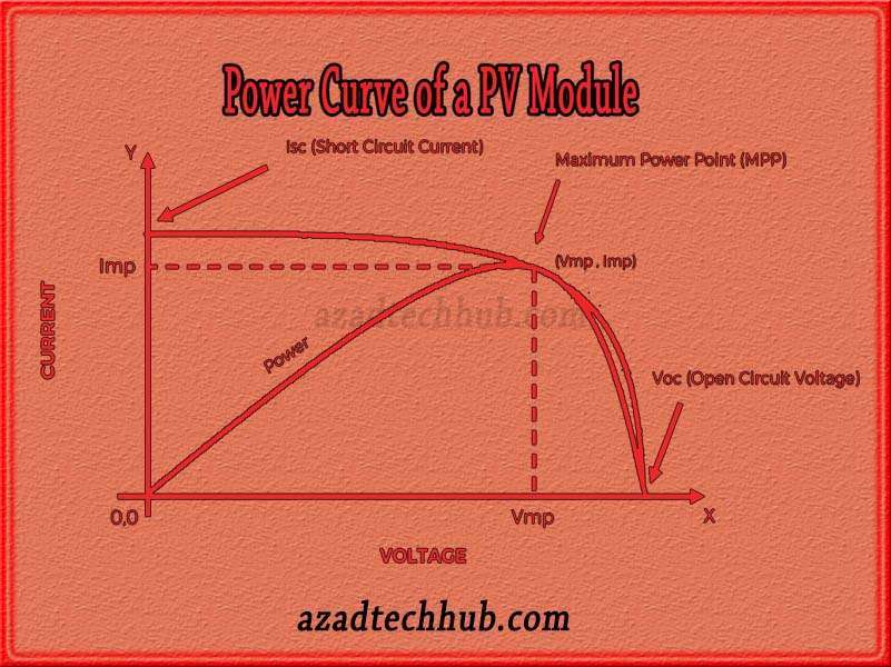
After a significant decrease in voltage, the voltages become stable and do not decrease further. The same scenario happens with the current, it stops increasing any further beyond that specific point. This point where both current and voltages stop changing is called the maximum power point of the solar system. At this specific point, the power transfer by the module is maximum and the current and voltages at this point are denoted by Imp and Vmp respectively.
So, if we draw this whole scenario on a curve we call it the IV curve of the solar panel. When we further increase the current on the curve, the current touch the “Y” axis. This is the maximum value of the current. This value is the short circuit current of a solar panel. This is represented by “Isc” on the nameplate of the solar panels. The IV curve of a PV module looks like the below figure.

Power Curve in a Solar Panel
As discussed above, maximum power transfers at the maximum power point. When we draw the power curve of a solar panel, power starts increasing with the increase in current and voltages. At a point where the power is maximum, it touches the IV curve of a solar panel. The same point we discussed above, calls this point the maximum power point. Beyond this point, the power starts decreasing and tends to zero when the open circuit voltages are achieved. When we draw both curves, the picture looks like below.

Want to know more about domestic solar system installations and their selection with tips and tricks, follow the link to learn more about solar system design considerations. Subscribe to our newsletters and articles for future coming posts in series with this post.
Follow us on LinkedIn”Electrical Insights” to get the latest updates in Electrical Engineering. You can also Follow us LinkedIn to see our latest posts.
