Schmitt Trigger: Important Types, Working & Applications
What is a Schmitt Trigger?
A Schmitt Trigger is a type of comparator-based circuit that incorporates positive feedback to achieve hysteresis, which is the ability to have different threshold voltage levels for signal rise and fall. It is commonly used in electronics to convert an analog input signal into a well-defined digital output signal.

Read More About
The Schmitt Trigger operates by comparing the input voltage level with two threshold voltages: the upper threshold (VUT) and the lower threshold (VLT). When the input voltage rises above the upper threshold, the output of the Schmitt switches to a high state.
It remains in this state until the input voltage falls below the lower threshold. Once the input voltage drops below the lower threshold, the output switches to a low state. The output remains low until the input voltage rises above the upper threshold again, and the cycle repeats.
By utilizing hysteresis, the Schmitt Trigger provides noise immunity and prevents false triggering. It is particularly useful in applications where a clean digital output signal is required, such as signal conditioning, debouncing mechanical switches, generating square wave signals in oscillators and timing circuits, and enhancing noise rejection in noisy environments.
Overall, the Schmitt Trigger is a versatile circuit that ensures reliable and stable digital output signals by incorporating hysteresis and threshold voltage levels.
How does a Schmitt Trigger work?
A Schmitt Trigger works by comparing the input voltage level with two threshold voltages: the upper threshold (VUT) and the lower threshold (VLT). It incorporates positive feedback to achieve hysteresis, which means that the threshold voltages for signal rise and fall are different.
The operation of a Schmitt Switch can be explained in the following steps:
Initialization: Assume the output of the Schmitt is initially in a known state, either high or low.
Input Voltage Comparison: The input voltage is compared with the upper and lower threshold voltages. If the input voltage is greater than the upper threshold voltage (VUT), the output of the Schmitt Trigger switches to a high state. Conversely, if the input voltage is less than the lower threshold voltage (VLT), the output switches to a low state.
Hysteresis: Once the output of the Schmitt Trigger switches to a high state, it remains high even if the input voltage decreases slightly below VUT. This hysteresis feature ensures noise immunity by preventing false triggering due to small fluctuations in the input signal. The output remains high until the input voltage falls below the lower threshold voltage (VLT).
Output State Transition: When the input voltage drops below VLT, the output of the Schmitt Trigger switches to a low state. It remains low even if the input voltage increases slightly above VLT, providing hysteresis for the rising edge of the input signal. The output stays low until the input voltage rises above the upper threshold voltage (VUT).
Repeating the Cycle: The cycle of switching between high and low output states continues as the input voltage crosses the upper and lower threshold voltages. The Schmitt Trigger maintains its output state until the input voltage exceeds the threshold levels, ensuring a well-defined digital output signal.
By incorporating hysteresis, the Schmitt provides noise immunity and prevents false triggering in applications where clean and stable digital signals are required. It is widely used in various electronic circuits, such as signal conditioning, debouncing mechanical switches, and enhancing noise rejection.
Schmitt Trigger circuit
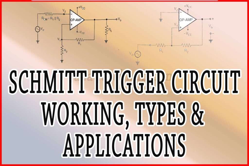
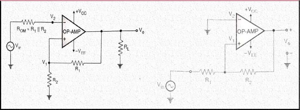
A Schmitt Trigger circuit is typically implemented using operational amplifiers (op-amps) and feedback resistors. Here is a general schematic diagram of a Schmitt Trigger circuit:

In this circuit, the operational amplifier is configured as a comparator. Here’s how it works:
Inverting and Non-Inverting Inputs: The inverting input (-) and non-inverting input (+) of the operational amplifier are connected through resistors R2 and R3, respectively. The input signal is typically applied to the inverting input, and the non-inverting input is set to a reference voltage level.
Feedback Resistors: Resistors R1 and R4 form a positive feedback loop. R1 is connected between the output and the inverting input, while R4 is connected between the inverting input and ground. These resistors set the upper and lower threshold voltages of the Schmitt Trigger circuit.
Threshold Voltage Levels: The upper threshold voltage (VUT) is determined by the voltage divider formed by R1 and R2, while the lower threshold voltage (VLT) is determined by the voltage divider formed by R3 and R4. These threshold voltages define the switching points of the Schmitt Trigger.
Output: The output of the operational amplifier represents the digital output of the Schmitt circuit. When the input voltage crosses the upper threshold voltage (VUT), the output switches to a high state (typically close to the supply voltage, +Vcc). When the input voltage drops below the lower threshold voltage (VLT), the output switches to a low state (typically close to ground).
By adjusting the values of resistors R1, R2, R3, and R4, the upper and lower threshold voltages of the Schmitt Trigger can be set according to the desired requirements of the specific application.
Note: The specific values of resistors and power supply connections may vary depending on the circuit design and application. Additionally, additional components such as capacitors may be included for stability and noise filtering purposes.
transistor based schmitt trigger circuit
A transistor-based Schmitt Trigger circuit can be implemented using bipolar junction transistors (BJTs) or field-effect transistors (FETs). Here, I will provide an example of a transistor-based Schmitt Trigger circuit using BJTs.
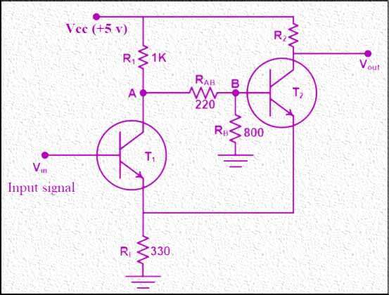
The circuit uses two NPN transistors in a feedback configuration to achieve hysteresis and provide digital output. Here is a general schematic diagram of a transistor-based Schmitt circuit:

Assuming the input voltage is denoted as “Vin” and the reference voltage is “Vref” (5V), we can analyze the behavior of the circuit. Initially, when Vin is zero, the transistor T1 remains in cutoff mode, meaning it does not conduct. By using the voltage divider rule, we determine that Vb (the voltage at the base of T2) is 1.98V. T2 starts conducting as a result, causing the output of the Schmitt trigger to be low. With a 0.7V voltage drop at the emitter terminal of T2, the base voltage of the transistor is calculated to be 1.28V.
Since the emitter terminals of both transistors are connected, they operate at the same level of 1.28V. This means T1 conducts when the input voltage is above 0.7V or 1.98V (1.28V + 0.7V). As a result, the input voltage needs to exceed 1.98V for T1 to conduct, leading to a high output from the Schmitt circuit.
Conversely, as the input voltage decreases, T1 will cutoff. In this scenario, T2 starts conducting, resulting in a low output from the Schmitt trigger. Thus, the circuit exhibits two threshold voltages: a lower threshold at 1.28V and a higher threshold at 1.98V.
Schmitt trigger Formulas
In the case of an inverting Schmitt trigger:
When the input voltage (Vin) is greater than the upper threshold voltage (VUT), the output (Vout) is low (VL).
When the input voltage is lower than the lower threshold voltage (VLT), the output is high (VH).
The upper threshold voltage (VUT) can be calculated as VUT = (R1 / (R1 + R2)) * VH.
The lower threshold voltage (VLT) can be calculated as VLT = (R1 / (R1 + R2)) * VL.
In the case of a non-inverting Schmitt trigger:
When the input voltage (Vin) is greater than zero, the output (Vout) is low (VL).
When the input voltage is lower than zero, the output is high (VH).
The output voltage (Vout) can be calculated as Vout = [(R2 / (R1 + R2)) * Vin] + [(R1 / (R1 + R2)) * VL].
When V1 (calculated from the above equation) is greater than zero, the output is high, meaning Vin > -((R1 / R2) * VL).
The Schmitt Trigger IC SN74LS14 is a 14-pin IC commonly used in various applications. It features six Schmitt input pins (1, 3, 5, 11, 13, 15) and six Schmitt output pins (2, 4, 6, 10, 12, 14). Pin 7 is connected to the ground, and pin 14 is the voltage supply pin (+5V).
Key features of the SN74LS14 IC include:
- It is a hex inverter, meaning it has six inverters.
- It operates at a voltage of 5V.
- The output current in the high state is typically -0.4mA, while in the low state, it is typically 8.0mA.
- It has low-level hysteresis voltage of 0.25V and high-level hysteresis voltage of 3.4V.
- The hysteresis voltage is typically 0.8V.
- The rise and fall times are both 12nS.
- The IC is available in 14-pin PDIP, GDIP, and PDSO packages.
Applications of Schmitt Trigger
Schmitt Triggers find applications in various electronic circuits where precise signal conditioning, noise immunity, and stable digital outputs are required. Let’s explore some of the common applications of Schmitt Triggers in detail:
Signal Conditioning: Schmitt Triggers are frequently used for signal conditioning purposes. They convert analog signals into well-defined digital signals, ensuring noise immunity and stability.
By setting appropriate upper and lower threshold voltages, Schmitt can accurately convert varying input voltages into high or low digital levels. This makes them useful in applications such as level shifting, amplitude detection, and signal amplification.
Debouncing: Mechanical switches and buttons can produce multiple contact bounces as they transition from an open to a closed state or vice versa. These bounces can generate false or erratic signals, leading to unreliable readings or malfunctions in digital circuits.
Schmitt Triggers are widely employed for debouncing switches by providing a stable digital output. The hysteresis characteristic of Schmitt Triggers ensures that a clean and steady digital signal is generated, eliminating the effects of switch bounce.
Oscillators and Timing Circuits: Schmitt Switches are capable of generating square wave signals, making them suitable for oscillator and timing circuit applications. By incorporating additional components such as resistors and capacitors, Schmitt Triggers can be configured to function as relaxation oscillators or astable multivibrator.
These circuits are commonly used for timing, clock generation, and frequency modulation in digital systems, communication devices, and timing applications.
Noise Immunity Enhancement: In electronic circuits, noise can interfere with the proper detection and interpretation of signals. Schmitt Triggers excel at enhancing noise immunity by providing hysteresis and a defined switching threshold.
The hysteresis ensures that the output state remains stable even in the presence of noise or signal fluctuations within a certain range. This characteristic enables reliable detection of signals, improves noise rejection, and enhances the overall performance of the circuit in noisy environments.
Digital-to-Analog Conversion: While Schmitt circuits are primarily used for analog-to-digital conversion, they can also be employed in certain cases for digital-to-analog conversion.
By employing a Schmitt Trigger in a feedback loop with a digital-to-analog converter (DAC), it is possible to generate analog voltage outputs that have well-defined switching levels. This configuration can be useful in applications where a precise analog signal is required with minimal noise sensitivity.
Input Signal Level Shifting: In some cases, it may be necessary to shift the level of an input signal to match the requirements of subsequent circuitry. Schmitt circuits can be used for level shifting applications, where they convert an input signal with one voltage range to an output signal with a different voltage range. By setting appropriate threshold voltages, the Schmitt Trigger ensures accurate and reliable level shifting of signals, allowing compatibility between different circuit sections.
These are just a few examples of the many applications of Schmitt Triggers in electronics. Their versatility, noise immunity, and ability to condition signals make them valuable components in various circuits, ensuring stable and reliable digital outputs.
Advantages of Schmitt Trigger
Schmitt Triggers offer several advantages that make them valuable components in electronic circuits. Here are some of the key advantages of Schmitt Triggers:
Noise Immunity: Schmitt circuits provide excellent noise immunity due to their hysteresis feature. The hysteresis ensures that the output state remains stable even in the presence of noise or signal fluctuations within a certain range. This characteristic makes Schmitt Triggers highly reliable in noisy environments, as they can effectively reject noise and interference, resulting in accurate and consistent digital outputs.
Debouncing Capability: Schmitt Triggers are widely used for debouncing mechanical switches. Mechanical switches often exhibit contact bounces, causing multiple rapid open-close transitions. Schmitt Triggers eliminate the effects of switch bounce by providing a stable digital output. This capability ensures clean and steady signals, preventing false triggering and enabling reliable operation of digital circuits.
Versatility: Schmitt Triggers are versatile components that can be employed in various electronic circuits. They can be used for signal conditioning, debouncing, oscillators, timing circuits, noise rejection, level shifting, and more. This versatility makes them suitable for a wide range of applications, allowing engineers to incorporate Schmitt circuits in different circuit designs and systems.
Simple Implementation: Schmitt Triggers can be easily implemented using commonly available components such as operational amplifiers and discrete transistors. Their straightforward design and operation make them cost-effective solutions for signal processing and conditioning. Additionally, their simplicity makes them accessible to both hobbyists and professionals, enabling easy integration into electronic designs.
Stable Digital Outputs: Schmitt Triggers provide well-defined digital output levels, ensuring stability and accuracy in signal processing. The use of hysteresis in Schmitt circuit allows for distinct threshold voltages for signal rise and fall, eliminating uncertainty and minimizing false triggering. This stability is crucial in applications where precise digital signals are required for subsequent circuitry or processing.
Low Power Consumption: Schmitt Triggers are known for their low power consumption. They are designed to operate efficiently with minimal power requirements, making them suitable for battery-powered devices and energy-conscious applications. Their low power consumption contributes to overall system efficiency and extends the battery life of portable electronic devices.
In summary, the advantages of Schmitt Triggers include noise immunity, debouncing capability, versatility, simple implementation, stable digital outputs, and low power consumption. These characteristics make Schmitt Triggers valuable components in various electronic circuits, enhancing performance, reliability, and signal processing capabilities.
Conclusion
In conclusion, the Schmitt Trigger is a versatile comparator-based circuit that utilizes hysteresis to provide distinct threshold voltages for signal rise and fall. With its unique characteristics, the Schmitt Trigger excels in signal processing, noise immunity, debouncing, and digital output generation. By incorporating hysteresis, it ensures stable circuit operation and reliable performance in the presence of noise and interference.
The Schmitt Trigger’s ability to condition analog signals and convert them into well-defined digital outputs makes it invaluable in various applications. It finds application in signal conditioning, where it enhances the accuracy and stability of signals. Additionally, it effectively eliminates switch bounce in debouncing applications, delivering clean and steady digital outputs.
Moreover, the Schmitt Trigger plays a key role in the generation of square wave signals, making it suitable for use in oscillators and timing circuits. Its noise rejection capabilities enable reliable signal detection in noisy environments, improving overall circuit performance.
Furthermore, the simplicity of implementing Schmitt Triggers using commonly available components ensures cost-effectiveness and ease of integration into electronic designs.
The Schmitt Trigger’s hysteresis-based operation, noise immunity, and stable digital outputs contribute to circuit stability and reliable signal processing. Its threshold voltage characteristics allow for precise and accurate switching, minimizing false triggering and ensuring dependable circuit operation.
In the realm of electronic designs, the Schmitt Trigger continues to be a fundamental building block, enabling noise-immune signal processing, precise digital output generation, and enhanced circuit stability. Its applications span across various domains, including signal conditioning, debouncing, oscillators, timing circuits, and noise rejection.
By harnessing the capabilities of the Schmitt Trigger, engineers and electronics enthusiasts can optimize their designs for superior performance, noise immunity, and reliability. Whether in industrial applications, consumer electronics, or communication systems, the Schmitt Trigger’s contributions to circuit design and signal processing make it an invaluable asset in the world of electronic engineering.
Subscribe to our Newsletter “Electrical Insights Daily” to get the latest updates in Electrical Engineering. You can also Follow us on LinkedIn and Facebook to see our latest posts on Electrical Engineering Topics.
Worth Read Posts
- Light Dependent Resistor
- What is a Variable Resistor?
- Lithium Ion Batteries
- CR2032 Battery
- Methods of Electrical Earthing
- Electrical Earthing Important Types
- Plant Factor, Plant Capacity Factor, and Load Factor
- Buck Converter Interview Questions
- DC DC Converter Interview Questions
- Transformer Electrical Interview
- Top 30 Op Amp Interview Questions
- Power Electronics Interview Questions
