NOR GATE: Important Types & Truth Tables
Read More About
Introduction:
The NOR gate is a fundamental component in digital electronics, serving as one of the basic logic gates used for processing binary information. With its versatile functionality and wide range of applications, the NOR gates play a crucial role in the design and operation of various electronic systems.
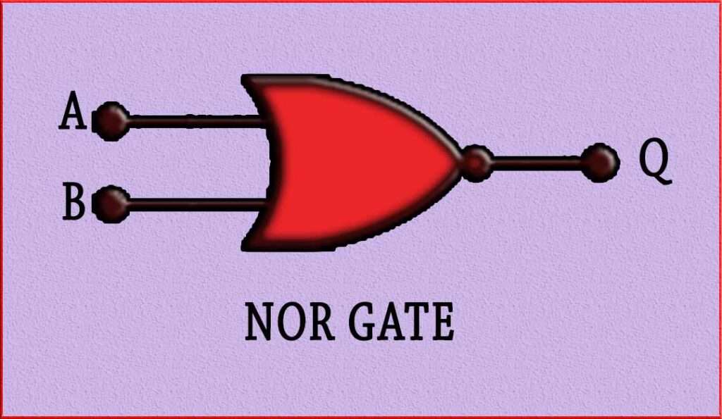
The term “NOR” stands for “NOT OR,” indicating its behavior as the negation of the OR gate. This gate produces an output signal based on the logical combination of its input signals. The NOR has the unique characteristic of being able to perform multiple logic operations, including inversion, OR, and NAND, making it a versatile building block for complex circuits.
In its simplest form, a NOR accepts two input signals and produces a single output signal. The output is high (logic 1) only when both inputs are low (logic 0). In other words, the output is false only when any of the inputs are true. This behavior can be represented by the Boolean expression A NOR B = Q.
The NOR’s truth table demonstrates its logical behavior, with the output being 1 only when all inputs are 0. This property makes it particularly useful for implementing logical functions such as logical negation, AND, and OR operations.
In practical applications, NOR gates find wide usage in various digital systems, including computer processors, memory circuits, control units, and communication devices. They are crucial in constructing complex logic circuits and can be combined to create more advanced gates or even entire processors.
The NOR’s simplicity, versatility, and ability to perform multiple logical operations make it an essential component in the world of digital electronics. Its presence and significance extend from basic electronic circuits to the most advanced computing systems, making it a cornerstone of modern technology.
nor gate truth table
Here’s the truth table for a NOR gate:
| Input A | Input B | Output |
| 0 | 0 | 1 |
| 0 | 1 | 0 |
| 1 | 0 | 0 |
| 1 | 1 | 0 |
In a NOR gate, the output is 1 (True) only when both inputs are 0 (False). For all other input combinations, the output is 0 (False). This behavior can be summarized as “If neither A nor B is True, then the output is True.”
The logic NOR gate performs logical multiplication on the complements of its inputs. Its Boolean expression is represented by the plus sign ( + ) with a line or overline ( ‾‾ ) above it, indicating the logical negation of the NOR gate. Therefore, the Boolean expression for a NOR is A + B = Q.
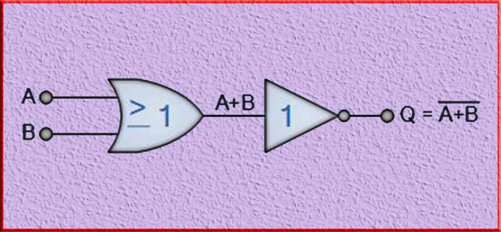
“If both A and B are not true (i.e., both inputs are false), then Q is true.”
Transistor Logic NOR Gate
In transistor logic, a NOR gate can be implemented using transistors to achieve the desired logical functionality. Transistors are the fundamental building blocks of digital circuits and can be used to create various logic gates, including the NOR gate.
The transistor implementation of a NOR gate typically involves using multiple transistors connected in a specific configuration. One common approach is to use two or more transistors in a series-parallel combination to achieve the NOR’s behavior.
The basic idea behind a transistor-based NOR is that the transistors are used as switches that control the flow of current through different paths based on the input signals. By appropriately connecting the transistors and biasing them, the desired logic function of the gate can be achieved.
The exact transistor circuit configuration and arrangement may vary depending on the specific transistor technology used (e.g., bipolar junction transistor or field-effect transistor) and the desired performance requirements. However, the underlying principle remains the same: leveraging the characteristics of transistors to create a logical NOR gate.
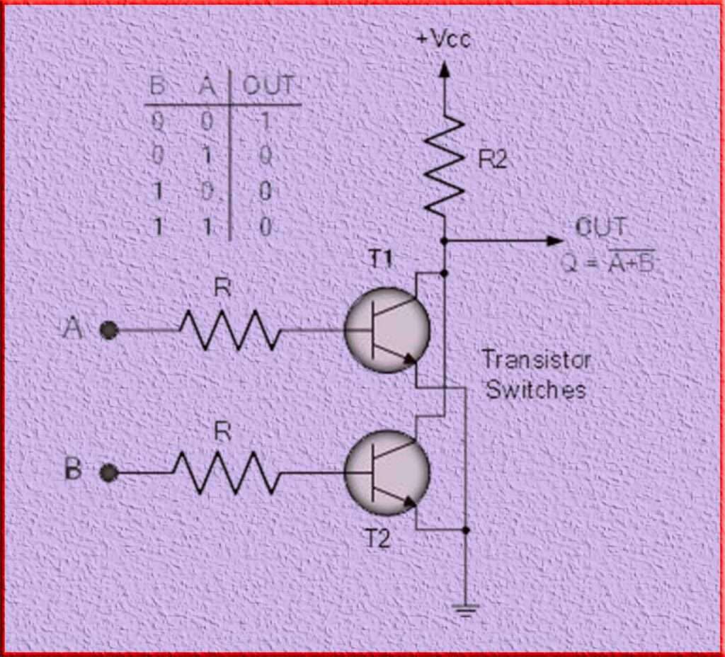
Implementing logic gates using transistors is a fundamental aspect of digital circuit design. It allows for the creation of complex computational systems by combining these basic building blocks in various configurations. The transistor-based gate plays a crucial role in this process, enabling the manipulation and processing of binary information in digital electronics.
A 2-input logic gate can be created using RTL (Resistor-Transistor Logic) with interconnected resistor-transistor switches. The inputs are directly connected to the transistor bases, and for the output Q to be active, both transistors must be in the cut-off state, meaning they are “OFF.”
Logic NOR gates are commonly used in digital circuits to achieve the desired logical function. They are represented by a symbol resembling a standard OR gate, with a circle or “inversion bubble” at the output, indicating the presence of a NOT (inversion) gate within the NOR circuitry.
The inversion bubble signifies that the output of the NOR gate is the logical negation of the OR gate’s output. This means that when the inputs A and B are both False (0), the output Q of the NOR will be True (1), and for all other input combinations, the output will be False (0).
3-input Logic NOR Gate Truth Table
Here’s the truth table for a 3-input logic NOR:
| Input A | Input B | Input C | Output |
| 0 | 0 | 0 | 1 |
| 0 | 0 | 1 | 0 |
| 0 | 1 | 0 | 0 |
| 0 | 1 | 1 | 0 |
| 1 | 0 | 0 | 0 |
| 1 | 0 | 1 | 0 |
| 1 | 1 | 0 | 0 |
| 1 | 1 | 1 | 0 |
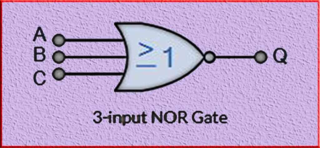
In a 3-input NOR gate, the output is 1 (True) only when all three inputs are 0 (False). For all other input combinations (i.e., at least one input is 1), the output is 0 (False). This behavior can be summarized as “If any of the inputs A, B, or C are True, then the output is False.”
4-input NOR Function Truth Table
Here’s the truth table for a 4-input NOR:
| Input A | Input B | Input C | Input D | Output |
| 0 | 0 | 0 | 0 | 1 |
| 0 | 0 | 0 | 1 | 0 |
| 0 | 0 | 1 | 0 | 0 |
| 0 | 0 | 1 | 1 | 0 |
| 0 | 1 | 0 | 0 | 0 |
| 0 | 1 | 0 | 1 | 0 |
| 0 | 1 | 1 | 0 | 0 |
| 0 | 1 | 1 | 1 | 0 |
| 1 | 0 | 0 | 0 | 0 |
| 1 | 0 | 0 | 1 | 0 |
| 1 | 0 | 1 | 0 | 0 |
| 1 | 0 | 1 | 1 | 0 |
| 1 | 1 | 0 | 0 | 0 |
| 1 | 1 | 0 | 1 | 0 |
| 1 | 1 | 1 | 0 | 0 |
| 1 | 1 | 1 | 1 | 0 |
In a 4-input NOR, the output is 1 (True) only when all four inputs are 0 (False). For all other input combinations (i.e., at least one input is 1), the output is 0 (False). This behavior can be summarized as “If any of the inputs A, B, C, or D are True, then the output is False.”
Commonly Available NOR Gate ICs
There are several commonly available integrated circuit (IC) packages that contain multiple NOR gates. Some of the popular ICs include:
74HC02: This IC contains four 2-input gates. It operates at high-speed and is compatible with both CMOS and TTL logic levels.
74LS02: This IC also contains four 2-input NOR gates. It is part of the TTL logic family and offers a low-power consumption option.
CD4001: This IC consists of four 2-input gates. It is part of the CMOS logic family and offers a wide supply voltage range.
CD4078: This IC contains four 2-input gates. It operates at a lower supply voltage and is suitable for low-power applications.
74HC266: This IC includes four 2-input NOR gates with open-drain outputs. It is commonly used for wired-AND or wired-NOR applications.
These are just a few examples of NOR gate ICs available in the market. Different ICs may have variations in features, voltage requirements, speed, and package types. It is important to refer to the datasheets and specifications of the specific ICs to determine their suitability for a given application.
Universal NOR Gate
The NOR gate is often referred to as a “universal” gate because it can be used to implement any logical function. This means that any other logic gate, such as AND, OR, NOT, NAND, XOR, etc., can be realized using only NOR gates.
By combining NOR in various configurations, it is possible to create circuits that perform complex logical operations. This property of the NOR gate simplifies circuit design and reduces the number of different gate types required in a system.
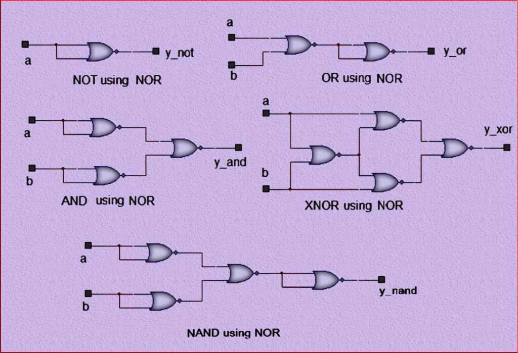
For example, to implement an AND gate using NOR gates, the inputs are connected to two separate gates, and their outputs are then connected to a third NOR. The resulting circuit behaves like an AND gate.
Similarly, an OR gate can be constructed by connecting the inputs to NOR gates and then connecting their outputs to a final gate. The resulting circuit functions as an OR gate.
By using additional NOR and appropriate combinations, other logic gates can also be implemented, providing flexibility and versatility in circuit design.
The universality of the NOR makes it an essential component in digital systems. Its ability to mimic other logic gates allows for efficient and compact designs, making it a valuable tool for engineers and designers in the field of digital electronics.
Logic Gates Using NOR
Here are few example logic gates which employ NOR gate.
Conclusion
In conclusion, the NOR gate is a fundamental logic gate in digital electronics that plays a vital role in processing binary information. Its ability to perform multiple logic operations, including inversion, OR, and NAND, makes it a versatile building block for designing complex circuits.
The NOR’s behavior can be summarized as producing a high output only when all inputs are low, making it useful for implementing logical negation and OR operations. Its truth table clearly illustrates its logical behavior and functionality.
NOR gates are commonly used in various digital systems, ranging from computer processors and memory circuits to control units and communication devices. They are essential in constructing complex logic circuits and can be combined to create more advanced gates or even complete processors.
The NOR’s simplicity, versatility, and widespread availability in integrated circuit packages make it a fundamental component in the field of digital electronics. Its significance spans from basic electronic circuits to advanced computing systems, demonstrating its status as a cornerstone of modern technology.
Overall, the NOR gate’s importance lies in its ability to process binary information, perform logical operations, and contribute to the functionality of countless electronic devices and systems.
Subscribe to our Newsletter “Electrical Insights Daily” to get the latest updates in Electrical Engineering. You can also Follow us LinkedIn to see our latest posts.
Frequently Asked Questions
What is a NOR gate in digital electronics?
A NOR gate is a logic gate in digital electronics that produces an output of “1” only when all of its inputs are “0.” Otherwise, it outputs “0.”
What is the logic symbol and truth table of a NOR gate?

The logic symbol of a NOR gate is a curved line with inputs on the left and the output on the right. The truth table for a NOR is:
How does a NOR gate function and what are its inputs and outputs?
A NOR gate performs an OR operation on its inputs, and then negates the result. It has two or more inputs and a single output. The output is “1” only when all the inputs are “0.”
What are the applications of a NOR gate in electronic circuits?
NOR gates are widely used in electronic circuits for various applications, including logic functions, memory circuits, multiplexers, timers, and in the design of processors and microcontrollers.
Can you explain the concept of NOR gate as a universal gate?
A NOR gate is considered a universal gate because it can be used to implement any logic function. By combining multiple NOR, all other basic logic gates such as AND, OR, and NOT can be constructed.
How is a NOR gate different from an OR gate?
The main difference between a NOR gate and an OR gate is that an OR gate outputs “1” when any of its inputs are “1,” while a NOR outputs “1” only when all of its inputs are “0.”
Are there any limitations or considerations when using a NOR gate?
When using NOR gates, it is important to consider the fan-out, which refers to the maximum number of gates that can be connected to the output of a NOR without causing signal degradation. Additionally, propagation delay and power consumption are factors to consider when designing circuits using NOR.
