TIP122 Pinout: A Comprehensive Guide
The TIP122 is a widely used NPN power transistor known for its versatile performance in various electronic applications. Understanding the TIP122 pinout is essential for correct circuit connections and efficient operation.
In this article, we will delve into the TIP122 Pinout, providing detailed information on each pin’s function and how to identify them on the device.
Read More

TIP122 Pinout Description
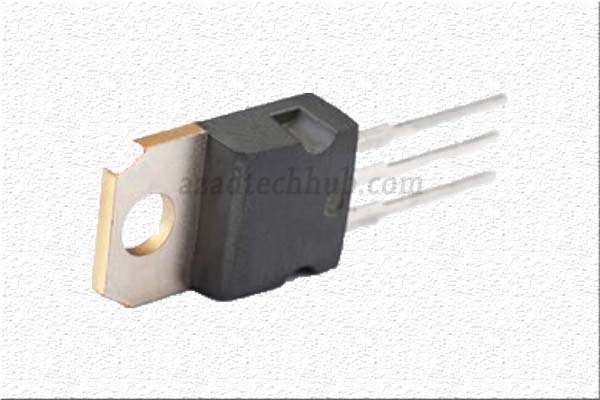
The TIP122 transistor is packaged in a TO-220 package, which features three leads that are essential for its proper functioning. Each lead performs a specific function, contributing to the overall behavior of the transistor in a circuit.
Collector (C) – The Collector pin, labeled “C” on the TIP122 transistor, is the output pin responsible for carrying the current from the load in a typical NPN transistor configuration. It is the primary pin through which the controlled current flows when the transistor is in its active mode. In most cases, the Collector is the center pin of the TO-220 package.
Base (B) – The Base pin, marked “B” on the TIP122, is the input pin that controls the transistor’s conductivity. By applying a small current to this pin, the transistor can be turned ON or OFF, allowing or blocking the current flow between the Collector and the Emitter. The Base is usually the left pin of the TO-220 package, when viewed with the front side (flat side) facing you and the leads pointing downward.
Emitter (E) – The Emitter pin, denoted “E,” serves as the reference point for the current flow in the transistor. It allows the current to exit the transistor when it is in the active state. The Emitter is typically the right pin of the TO-220 package when looking at it as described above.
Identifying the TIP122 Pinout
To correctly identify the TIP122 Pinout, follow these steps:
Hold the transistor with the front side (flat side) facing you and the leads pointing downward.
- The pin in the center is the Collector (C).
- The pin on the left side is the Base (B).
- The pin on the right side is the Emitter (E).
It is crucial to confirm the pinout before soldering or connecting the TIP122 in your circuit to avoid potential damage to the transistor or other components.
Applications of TIP122 Transistor
The TIP122 transistor’s versatility in various applications makes it highly popular among electronics enthusiasts and professionals alike. Some common applications include:
- High-power switching circuits.
- Motor control systems.
- Audio amplifiers.
- LED driving circuits.
- Solenoid control circuits.
Understanding the TIP122 pinout is essential for proper connections and efficient performance in electronic circuits. The Collector, Base, and Emitter pins play critical roles in determining the transistor’s behavior. By correctly identifying the TIP122 Pinout and integrating the TIP122 into your circuits, you can harness its power and versatility for a wide range of applications.
Whether you are a hobbyist or a seasoned engineer, the TIP122 transistor’s reliability and performance will undoubtedly be valuable in your electronic projects.
Related Posts:
- Floating Gate Transistor: Best Features & Applications
- TIP120 Transistor Pinout, Datasheet and Equivalent
- TIP122 Transistor Pinout, Datasheet & Applications
- Transistors BC547: Important Guide to Pinout
- C1815 Datasheet: Important Features to Know About
- S8050 Transistor: Best Functions, Specifications, and Applications
Follow us on LinkedIn”Electrical Insights” to get the latest updates in Electrical Engineering. You can also Follow us LinkedIn and Facebook to see our latest posts on Electrical Engineering Topics.
