Calculating Power Factor Correction: A Comprehensive Guide
Calculating power factor correction is a crucial step in optimizing energy efficiency and reducing electricity costs in industrial and commercial setups. Power factor correction involves adjusting the power factor of a system to bring it closer to unity, which can lead to improved equipment performance and reduced losses.

Read More
In this guide, we will delve into the process of calculating power factor correction, using simple equations and real-world examples to enhance understanding. Here is an overview of what we will learn in detail.
Calculating Power Factor Correction
Power factor correction is the process of improving the power factor of an electrical system by adjusting reactive power to match real power. To calculate power factor correction, follow these steps:
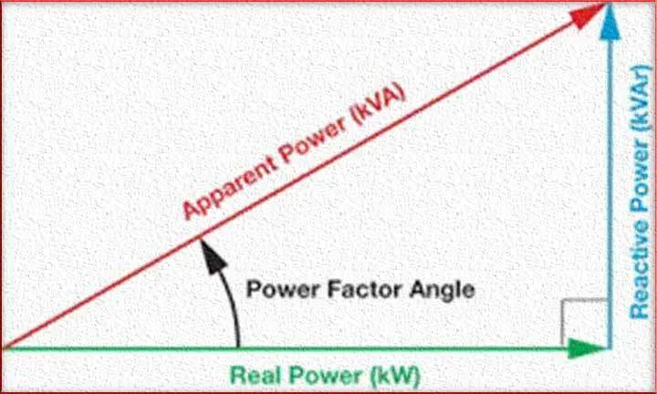
Step 1: Determine the Current Power Factor: Measure the existing power factor of the system. The power factor is the cosine of the angle between the real power (kW) and apparent power (kVA). It can be calculated using the formula:
Power Factor (PF) = Real Power (kW) / Apparent Power (kVA)
Step 2: Calculate the Required Power Factor: Decide on the desired power factor that you want to achieve. This is typically close to 1, as a power factor of 1 represents perfect power factor correction (unity power factor).
Step 3: Calculate the Reactive Power to Be Corrected: Find the reactive power that needs to be corrected by using the following formula:
Reactive Power to Be Corrected (kVAR) = Apparent Power (kVA) * (Current Power Factor – Desired Power Factor)
Step 4: Select the Capacitor Size: Choose the appropriate capacitor size to correct the reactive power. Capacitors are used to provide leading reactive power, offsetting lagging reactive power.
Step 5: Calculate the Required Capacitor Rating: Determine the required capacitor rating in kilovolt-amperes reactive (kVAR) using the formula:
Capacitor Rating (kVAR) = Reactive Power to Be Corrected (kVAR)
Step 6: Installation: Install capacitors of the calculated size in the system. Ensure proper connection and safety measures.
What is Power Factor Correction
Power factor correction is the process of increasing the power factor of a system by adding capacitors or other reactive elements to the circuit. This adjustment minimizes the phase difference between the voltage and current waveforms, thereby reducing the reactive power and improving the overall power factor.
Equations in Calculating Power Factor Correction
To calculate the required power factor correction, you’ll need the following equations:
- Reactive Power (Q): Before calculating power factor correction, determine the reactive power of the system using the formula
- Reactive Power (Q) = Apparent Power (S) x sin(θ)
Where θ is the phase angle between the voltage and current.
- Desired Power Factor (PFd): Decide on the desired power factor after correction.
- Real Power (P): Calculate the real power of the system:
- Real Power (P) = Apparent Power (S) x Power Factor (PF)
Calculating Required Capacitance for Power Factor Correction
Once you have the above values, you can determine the required capacitance for power factor correction:
- Desired Reactive Power (Qd): Calculate the desired reactive power after correction:
- Desired Reactive Power (Qd) = Apparent Power (S) x √(1 – Desired Power Factor (PFd)^2)
- Required Capacitance (C): Use the following formula to calculate the required capacitance for power factor correction:
- Required Capacitance (C) = Desired Reactive Power (Qd) / (2π x Frequency x Voltage^2)
Where Frequency is the frequency of the AC power supply and Voltage is the line voltage.
Calculating Power Factor Correction Example
Let’s consider an industrial facility with an apparent power (S) of 1000 kVA and a power factor (PF) of 0.85. The facility aims to achieve a power factor of 0.95.
Calculate Reactive Power (Q):
Q = S x sin(θ)
Since PF = cos(θ),
θ = acos(PF) = acos(0.85) ≈ 31.79°
Q = 1000 kVA x sin(31.79°) ≈ 527.74 kVAR
Calculate Desired Reactive Power (Qd):
Qd = S x √(1 – PFd^2)
Qd = 1000 kVA x √(1 – 0.95^2) ≈ 87.13 kVAR
Calculate Required Capacitance (C):
Given Frequency ≈ 50 Hz and Voltage ≈ 400 V,
C = 87.13 kVAR / (2π x 50 Hz x (400 V)^2) ≈ 0.00109 F ≈ 1090 μF
By adding a capacitance of approximately 1090 μF, the facility can achieve the desired power factor of 0.95.
In conclusion, calculating power factor correction involves understanding the current power factor, desired power factor, and using appropriate equations to determine the required capacitance for optimal correction.
By utilizing these equations and real-world examples, you can effectively implement power factor correction strategies and enhance energy efficiency in your electrical systems.
Follow us on LinkedIn”Electrical Insights” to get the latest updates in Electrical Engineering. You can also Follow us on LinkedIn and Facebook to see our latest posts on Electrical Engineering Topics.
Worth Read Posts
- What is a Variable Resistor?
- Lithium Ion Batteries
- CR2032 Battery
- Methods of Electrical Earthing
- Electrical Earthing Important Types
- Plant Factor, Plant Capacity Factor, and Load Factor
- Buck Converter Interview Questions
- DC DC Converter Interview Questions
- Transformer Electrical Interview
- Top 30 Op Amp Interview Questions
- Power Electronics Interview Questions
Explore TheNepal for an authentic glimpse into Nepali culture and lifestyle!
