
How to Check Power Factor: Best Methods & Procedure
Knowing how to check power factor is important when troubleshooting motors, transformers, HVAC systems, industrial loads, and electrical bills. A low power factor means the installation draws more current than necessary for the useful power being delivered. This can increase cable losses, voltage drop, transformer loading, and in some commercial or industrial systems, utility charges.
The good news is that power factor can be checked in several practical ways. You can calculate it from voltage, current, and real power, use a dedicated power factor meter, or perform a three-phase measurement with a power analyzer.
How to Check Power Factor
| Method | Equipment Needed | Typical Accuracy | Best Application |
|---|---|---|---|
| Formula calculation | Wattmeter, voltmeter, ammeter | Good | Basic testing |
| Power factor meter | PF meter | High | Panels and industrial loads |
| Clamp power meter | Clamp meter with PF function | High | Field troubleshooting |
| Power analyzer | Three-phase analyzer | Very high | Surveys and detailed analysis |
| Two-wattmeter method | Two wattmeters | Good | Three-phase systems |
| Utility meter | Smart/energy meter | Varies | Billing and monitoring |
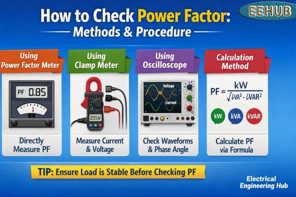
Table of Contents
Table of Contents
What Is Power Factor?
Power factor is the ratio between real power and apparent power in an AC electrical system.
The basic power factor formula in electrical systems is:
Power Factor (PF) = Real Power (kW) ÷ Apparent Power (kVA)
For a purely resistive load, the power factor is close to 1.00. Motors, transformers, compressors, pumps, and other inductive equipment normally have a lagging power factor.
For example, if a motor consumes 8 kW and its apparent power is 10 kVA:
PF = 8 ÷ 10 = 0.80
The same value can be expressed as a power factor percentage:
0.80 × 100 = 80%
A higher value generally indicates better utilization of the electrical supply.
How to Check Power Factor Using the Basic Formula
One of the simplest methods is calculating power factor from measured real power and apparent power.
First, measure the real power in watts or kilowatts. Then determine the apparent power from the system voltage and current.
For a single-phase circuit:
S = V × I
For a three-phase circuit:
S = √3 × VL × IL
where:
- S = apparent power in VA
- V = voltage in volts
- I = current in amperes
- VL = line-to-line voltage
- IL = line current
The next step is to divide real power by apparent power.
Power Factor Example
Suppose a three-phase motor operates at:
- Line voltage = 400 V
- Line current = 18 A
- Real power = 9 kW
Apparent power is:
S = 1.732 × 400 × 18 = 12.47 kVA
Therefore:
PF = 9 ÷ 12.47 = 0.72
The motor is operating at approximately 0.72 power factor, which is relatively low for many industrial applications.
This calculation is useful for determining power factor without a dedicated instrument.
How to Measure Power Factor With a Meter
A dedicated power factor meter measures voltage and current while determining their phase relationship. Modern instruments can display real power, reactive power, apparent power, frequency, and PF on the same screen.
A power factor meter is useful because it eliminates much of the manual calculation involved in field testing.
To perform power factor measurement:
- Confirm the voltage and current ratings of the test equipment.
- Connect the voltage leads according to the manufacturer’s instructions.
- Place the current clamp around the correct conductor.
- Energize the circuit.
- Select the PF measurement function.
- Allow the reading to stabilize.
- Record PF, voltage, current, kW, and kVA.
- Repeat the test under different load conditions.
A power factor metre is particularly useful in distribution panels where the load changes throughout the day.
How to Check Power Factor With a Multimeter
A standard digital multimeter normally cannot directly measure power factor. It can measure voltage and, on some models, current, but PF also depends on the phase relationship between voltage and current.
Therefore, simply measuring voltage and current with a conventional multimeter is not enough.
For example, measuring 230 V and 10 A gives:
230 × 10 = 2,300 VA
This tells you apparent power, not real power. If the load consumes 1,610 W, then:
PF = 1,610 ÷ 2,300 = 0.70
A multimeter can therefore support the calculation, but you also need a wattmeter, energy meter, or suitable power analyzer to obtain real power.
A clamp meter with a built-in power function is a better option for field work. It can simultaneously measure voltage, current, watts, and PF.
How to Find Power Factor in a Three-Phase System
For a balanced three-phase system, use:
PF = kW ÷ (√3 × kV × A)
Consider a 415 V industrial load drawing 25 A and consuming 12 kW.
Apparent power:
S = 1.732 × 415 × 25 = 17.97 kVA
Therefore:
PF = 12 ÷ 17.97 = 0.67
This is a useful procedure for finding power factor in three-phase equipment.
For unbalanced systems, measuring each phase separately is preferable. A three-phase power analyzer can measure individual phase voltage, current, active power, reactive power, and PF.
How to Find Power Factor of a Motor
Motor power factor changes with loading. A lightly loaded induction motor can have a considerably lower PF than the same motor operating near its rated load.
The best way to determine power factor for a motor is to measure:
- Line voltage
- Line current
- Real power
- Reactive power
- Apparent power
- Frequency
- Motor load
For example, a 15 kW motor may operate at approximately 0.82 to 0.90 PF depending on its design and operating load. The nameplate may provide a rated PF, but the actual current power factor can be different.
Therefore, nameplate data should not replace an actual measurement when conducting a power factor survey and analysis.
How to Determine Power Factor From Voltage and Current
Voltage and current alone do not provide enough information to calculate PF unless the phase angle or real power is also known.
If the phase angle is available:
PF = cos θ
For example, if the phase angle is 36.87°:
PF = cos(36.87°) ≈ 0.80
Another method is to use real power:
PF = P ÷ S
This is generally more practical in the field because modern power meters calculate these values automatically.
Two-Wattmeter Method for Three-Phase Power Factor
The two-wattmeter method is commonly used for measuring three-phase power in a three-wire system.
If the two wattmeter readings are W1 and W2:
tan φ = √3(W1 − W2) ÷ (W1 + W2)
Then:
PF = cos φ
For example, if:
- W1 = 8 kW
- W2 = 4 kW
Then total real power is 12 kW.
The phase angle can be determined from the wattmeter readings, after which the power factor can be calculated. This technique is useful for electrical testing and laboratory work, although modern power analyzers are usually faster in field applications.
How to Measure Power Factor at Home
For a home installation, the easiest approach is normally a plug-in energy meter or a suitable smart energy monitor that reports watts, VA, and PF.
Do not attempt to open a residential distribution board simply to measure PF unless you are qualified to work on energized electrical equipment.
For a household appliance, connect an appropriate energy meter between the appliance and supply where practical. A refrigerator, washing machine, air conditioner, or induction motor may show a different PF because electronic and motor loads have different electrical characteristics.
Typical values can vary widely:
| Load Type | Typical PF Range |
|---|---|
| Incandescent lamp | 0.95–1.00 |
| Heating element | 0.95–1.00 |
| Modern LED driver | 0.90–0.99 |
| Refrigerator compressor | 0.60–0.90 |
| Induction motor | 0.70–0.95 |
| Computer power supply | 0.60–0.99 |
| Large commercial motor | 0.80–0.95 |
These are typical engineering ranges, not guaranteed values for every appliance.
Power Factor in an Electricity Bill
Many residential customers are billed mainly according to energy consumption in kWh, so PF may not appear as a separate charge.
Commercial and industrial customers can face different tariff structures. Utilities may apply demand charges, reactive energy charges, or power factor penalties depending on the tariff and local regulations.
For this reason, there is no single universal “power factor rate.” The applicable threshold and penalty depend on the utility, customer category, contract, and tariff schedule.
If your bill contains kWh, kVAh, maximum demand, or reactive energy information, compare these values with the utility’s current tariff document rather than assuming a fixed penalty.
Power Factor Measurement Circuit
A basic power factor measurement circuit requires voltage and current measurements from the same electrical load.
The measurement arrangement normally includes:
- Voltage sensing connection
- Current transformer or current clamp
- Power measurement circuit
- Phase-angle measurement
- Display or data logger
Modern power factor analyzers combine these functions inside one instrument. For higher-voltage systems, properly rated current transformers and voltage transformers may be required.
Never connect test equipment beyond its rated category or voltage rating.
How to Test Power Factor Safely
Electrical safety should come before any power checking procedure.
Before measuring:
- Identify the system voltage and phase configuration.
- Check the CAT rating of the instrument.
- Inspect test leads and clamps.
- Wear appropriate PPE.
- Follow the manufacturer’s connection sequence.
- Avoid exposed energized conductors whenever possible.
- Record readings only after they stabilize.
- Compare measurements with equipment ratings and historical data.
For industrial panels, a qualified electrical professional should perform energized measurements.
Power Factor Analysis and Monitoring
A single PF reading gives only a snapshot. Power factor monitoring provides much more useful information because electrical loads change throughout the day.
A power analyzer can record PF along with kW, kVA, kVAR, voltage, current, and frequency. This makes it possible to identify periods of poor power factor.
A useful power factor survey may include:
- Morning startup
- Peak production
- Minimum production
- Motor starting
- HVAC operation
- Capacitor bank switching
- Night or low-load operation
If PF falls sharply during certain operating periods, the cause may be an oversized transformer, lightly loaded motors, variable-speed drives, welding equipment, or an incorrectly controlled capacitor bank.
Improve system efficiency by learning practical strategies for power factor improvement, including capacitor sizing and correction methods.
Measuring Power Factor Correction
After installing correction equipment, such as capacitor banks, measure the system again under the same operating conditions.
Suppose an industrial load initially consumes 100 kW at 0.70 PF.
Initial apparent power:
100 ÷ 0.70 = 142.9 kVA
After correction to 0.95 PF:
100 ÷ 0.95 = 105.3 kVA
The apparent-power requirement falls by about:
142.9 − 105.3 = 37.6 kVA
This reduction can lower current and reduce losses in appropriately designed systems.
However, capacitor correction must be designed carefully. Harmonic-producing loads can interact with capacitors and create resonance problems.
Before selecting correction equipment, review this guide to power factor improvement for practical sizing, application, and troubleshooting considerations.
Common Mistakes When Checking Power Factor
Several mistakes can produce misleading results.
Using voltage × current as real power
Voltage multiplied by current gives apparent power, not watts, unless the load has a PF of 1.
Measuring voltage and current from different phases
The voltage and current measurements must correspond to the same circuit and correct phase relationship.
Relying only on the motor nameplate
The nameplate usually provides rated operating information. Actual PF changes with motor loading.
Ignoring harmonics
Distorted current waveforms can make simple phase-angle calculations less accurate. A true power analyzer is better for nonlinear loads.
Checking only one operating condition
A motor may show 0.85 PF at one load and a much lower value when lightly loaded.
Quick Power Factor Calculation Reference
| Known Values | Formula |
|---|---|
| kW and kVA | PF = kW ÷ kVA |
| Phase angle | PF = cos θ |
| Single-phase V and I | kVA = V × I ÷ 1,000 |
| Three-phase V and I | kVA = √3 × V × I ÷ 1,000 |
| PF percentage | PF × 100 |
| Real power | kW = kVA × PF |
These equations cover most basic power factor calculations used in electrical engineering.
FAQs
1. How do you calculate power factor?
Divide real power in kW by apparent power in kVA. For example, 8 kW ÷ 10 kVA gives a PF of 0.80.
2. Can I measure power factor with a normal multimeter?
No. A conventional multimeter generally measures voltage and resistance and may measure current, but it does not normally measure phase angle or real power. Use a power meter or power analyzer for direct measurement.
3. What is a good power factor?
A PF close to 1.00 is ideal. In many industrial applications, values around 0.90 to 0.95 or higher are generally considered desirable, but the acceptable level depends on the equipment and utility requirements.
4. How do I calculate power factor from an electricity bill?
If the bill provides kWh and kVAh for the same billing period, an approximate relationship is:
PF = kWh ÷ kVAh
However, billing calculations vary by utility, so use the utility’s definitions and tariff rules when assessing charges.
5. How do I determine power factor for a three-phase motor?
Measure line voltage, line current, and real power under a stable operating condition. Then calculate apparent power using √3 × V × I and divide real power by apparent power.
Final Takeaway
The most reliable way to check power factor is with a dedicated power meter, clamp power meter, or power analyzer. For basic calculating power factor, use real power and apparent power, while the phase-angle method can be used when the phase relationship is known.
For three-phase systems, remember the √3 factor, and for motors, always consider actual loading because PF changes with operating conditions. Regular power factor monitoring can also reveal inefficient loads before they create excessive current, losses, or utility-related costs.
If your measurements show a low PF, explore practical power factor improvement methods before choosing capacitors or other correction equipment.
Get new guides in your feed. Follow Electrical Insights on LinkedIn for new electrical standards guides, calculators and design tips from Azad Circuit Hub.
HowToCheckPowerFactor, #PowerFactor, #PowerFactorTesting, #ElectricalEngineering, #PowerFactorCorrection, #PowerQuality, #ElectricalMeasurements, #PowerFactorMeter, #EnergyEfficiency, #ElectricalTesting
