Thyristor Rectifier Circuit: A Comprehensive Guide
A thyristor rectifier circuit, often known as a thyristor-based rectifier or just an SCR rectifier, is an essential electrical circuit used to convert alternating current (AC) into direct current (DC). Numerous industrial applications, such as power supplies, motor drives, battery charging systems, and others, frequently use this kind of rectification technology.

Read More About
We will look into the operation, components, and applications of a thyristor rectifier circuit in this article, as well as related terms like thyristors, rectification, and power electronics.
Thyristor Rectifier Circuit
Components of a Thyristor Rectifier Circuit
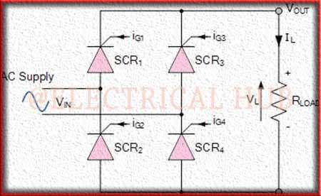
An SCR (Silicon Controlled Rectifier) rectifier circuit, sometimes referred to as a thyristor rectifier circuit, is made up of a number of essential parts that work together to transform alternating current (AC) into direct current (DC). These parts make sure that AC voltage is rectified under control.
The main elements of a typical thyristor rectifier circuit are as follows:
Thyristors (SCRs): The thyristor rectifier circuit is powered by thyristors. These semiconductor devices are useful for rectifying AC since they only allow current to flow in one direction. One thyristor is normally utilized for each half-cycle of the AC waveform and pairs of them are typically used. By providing a gate current, which enables current to move from the anode to the cathode, they are brought into conduction.
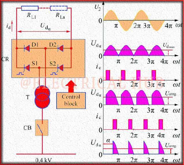
Transformer: A transformer is frequently used in thyristor rectifier circuits to scale down the input AC voltage to a level appropriate for the application. This transformer aids in maintaining the desired output DC voltage. Additionally, it offers separation between the input and output, enhancing security and lowering noise.
Diode Bridge (Optional): A diode bridge, albeit it is not always present, can be used with thyristors to rectify the AC voltage’s positive and negative half-cycles. The full-wave rectification offered by the diode bridge ensures a more consistent DC output. It is made up of a number of diodes grouped in a bridge arrangement.

Filtering Components: The rectified DC voltage could still contain some ripple or AC components. In order to smooth down the voltage and lessen ripple, filtering elements like capacitors and inductors are frequently added to the circuit. These elements aid in producing a steady, uninterrupted DC output.
Control Circuitry: A control circuit is frequently included into the thyristor rectifier circuit to ensure accurate timing and control over the thyristors’ firing. To ensure precise and synchronized rectification, this control circuit creates the gate signals required to activate the thyristors at the appropriate points in the AC cycle.
Protection Devices: To protect the circuit and the equipment attached to it, several protection devices may be incorporated. To stop the thyristors from overheating, this can incorporate overcurrent protection, overvoltage protection, and temperature monitoring.
Cooling System: A cooling system is necessary for high-power thyristor rectifier circuits to dissipate the heat produced during operation. According to the power rating and application, cooling techniques may include heat sinks, fans, or liquid cooling systems.
Output Terminals: The rectified DC voltage for external devices or loads is provided by the DC output terminals. The thyristor triggering, transformer ratio, and filtering elements all affect the output voltage level.
To transform the input AC power into a steady and controlled DC output, these components collaborate in an organized manner. In several industrial applications, including power supply, motor drives, battery charging systems, and welding equipment, where precise control and effective AC to DC power conversion are essential, thyristor rectifier circuits are frequently utilized.
Operation of a Thyristor Rectifier Circuit
The regulated conversion of alternating current (AC) into direct current (DC) is essential to the operation of a thyristor rectifier circuit, sometimes referred to as an SCR (silicon-regulated Rectifier) rectifier circuit. The operation of a thyristor rectifier circuit is described in detail below:
Triggering Phase:
Initialization: Initialising the thyristors starts the procedure. All thyristors are initially in the off state, which is non-conducting.
Gate Triggering: Thyristors need to be forced into conduction in order to begin conducting. Applying a gate current to the thyristor accomplishes this. A brief, carefully timed pulse is often applied as the gate signal at the desired point in the AC cycle.

Synchronization: Effective synchronization is essential. To guarantee that the thyristors conduct during the positive half-cycle of the AC voltage, gate triggering must take place at the proper position in the AC waveform. For the rectification to be effective, this timing is crucial.
Rectification Phase:
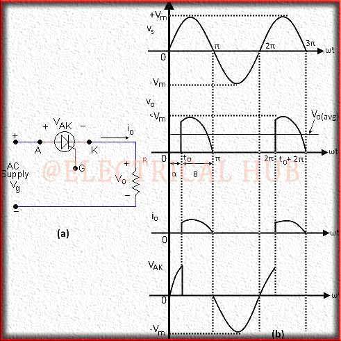
Thyristor Conduction: During the positive half-cycle of the AC voltage, the thyristors conduct once activated and let current to flow in one direction (from anode to cathode). By doing this, the AC voltage is efficiently rectified into a pulsing DC voltage.
Blocking Negative Half-Cycle: Thyristors are designed to be unidirectional, therefore the negative half-cycle of the AC voltage is blocked because they are unidirectional. The thyristors do not conduct during the negative half-cycle, guaranteeing that only the positive half-cycle is transmitted.
Output Phase:
Pulsating DC Output: The output voltage is a pulsating DC voltage as a result of thyristor conduction during the positive half-cycle and blocking during the negative half-cycle. Due to the alternating nature of the AC input, the voltage is currently not stable and smooth; it exhibits ripple.
Filtering: Following the rectification stage, capacitors and inductors are frequently linked to produce a more steady and continuous DC output. A cleaner and more reliable DC output is produced as a result of these components’ ability to smooth the voltage by lowering the ripple.
Control and Regulation (Optional):
Some thyristor rectifier circuits include control and regulation components to allow for necessary adjustments to the output voltage or current. To regulate the amount of power given to the load, this may entail changing the triggering angle of the thyristors.
Protection and Monitoring (Optional):
Protection mechanisms and monitoring circuits are frequently used in applications to guarantee the security and dependability of the rectifier circuit. To avoid the thyristors from overheating, they may incorporate temperature monitoring, overcurrent protection, and overvoltage protection.
Load Connection:
The output terminals of the thyristor rectifier circuit are linked to the load, which may be machinery, motors, or other devices. The circuit’s stable DC power is sent to the load.
Applications of Thyristor Rectifier Circuits
Due to their capability to effectively convert alternating current (AC) into direct current (DC) while offering fine control over the output voltage or current, thyristor rectifier circuits, also known as SCR (Silicon Controlled Rectifier) rectifier circuits, have a wide range of applications in various industries. The following are some notable thyristor rectifier circuit applications:
Commercial Power Supply:
Industrial machinery and equipment require reliable, controllable DC power, which is frequently provided via thyristor rectifier circuits. They are critical in sectors including manufacturing, chemical processing, and metallurgy where processes depend on reliable electricity.
Systems for charging batteries:
Thyristor rectifiers are used to effectively transform AC power into the DC power required to charge batteries in battery charging stations for electric cars (EVs) and backup power systems. These rectifiers provide exact control over the charging conditions, resulting in the best battery health.
Drives and controls for motors:
Motor drives and control systems use thyristor rectifiers. They are useful in applications like conveyor systems, lifts, and industrial automation because they transform AC power into variable DC voltage, which enables precise control of motor speed and torque.
Welding supplies:
Thyristor rectifiers are frequently used in welding machines to supply high-power, reliable DC current for welding procedures. The welding current is precisely controlled, resulting in high-quality welds and little energy use.
UPSs: Uninterruptible Power Supplies
Thyristor rectifiers are used in UPS systems to transform AC power into DC power, which is then stored in batteries. The saved DC power is subsequently converted back to AC power after a power loss to maintain the uninterrupted operation of vital machinery.
Processes that use electrochemistry
Thyristor rectifiers are used in the electrochemical industries to deliver precise DC power for controlling the deposition of metals and other materials onto substrates during electroplating, anodizing, and other electrochemical processes.
Smelting of aluminium:
Aluminium smelting plants heavily rely on thyristor rectifier circuits. For the electrolysis method that separates the aluminium from alumina ore, they supply the high-power, high-current DC required.
Heating using High-Frequency Induction:
Thyristor rectifiers offer the controlled DC power required to produce intense localised heating in applications where high-frequency induction heating is important, such as in metal heat treatment and forging.
Systems for Renewable Energy:
Wind turbines and solar power inverters are two examples of renewable energy systems that use thyristor rectifiers. They transform these sources’ unstable AC output into consistent DC power for grid connectivity or battery storage.
Testing and Research Facilities:
In laboratories, thyristor rectifiers are employed for a variety of research and testing tasks, such as electrochemical studies, material testing, and instrument calibration.
Traction Systems for Railroads
Thyristor rectifiers are used in electric train systems to change the AC voltage from overhead lines into DC power for traction motors. This makes it possible to manage train speed precisely and use regenerative braking.
Defence and aerospace
In aerospace and defence applications, thyristor rectifiers are used to supply reliable power for avionics, radar systems, and missile guidance systems.
These applications demonstrate the versatility and importance of thyristor rectifier circuits in modern industries, where efficient and controlled conversion of AC to DC power is essential for various processes and equipment.
Finally, a thyristor rectifier circuit is an essential component of contemporary power electronics. It is vital in a wide range of applications across different industries due to its ability to convert AC to DC power effectively. Engineers and technicians can use thyristor rectifier circuits to increase energy conversion and control in a variety of systems by comprehending their parts, operations, and applications.
Subscribe to our Newsletter “Electrical Insights Daily” to get the latest updates in Electrical Engineering. You can also Follow us on LinkedIn and Facebook to see our latest posts on Electrical Engineering Topics.
Worth Read Posts
