IEC 61439 Temperature Rise Limits for Busbars
Temperature rise is one of the key design checks for a low-voltage switchgear and controlgear assembly. Busbars carry high current, so their resistance, joint quality, enclosure design, and heat dissipation can have a direct effect on operating temperature.
Temperature Rise Limits for Busbars under IEC 61439 should not be treated as one fixed value for every busbar. The standard considers the complete assembly, including conductors, connections, terminals, operating devices, and accessible surfaces. The permitted temperature rise also depends on the relevant component and applicable product requirements.
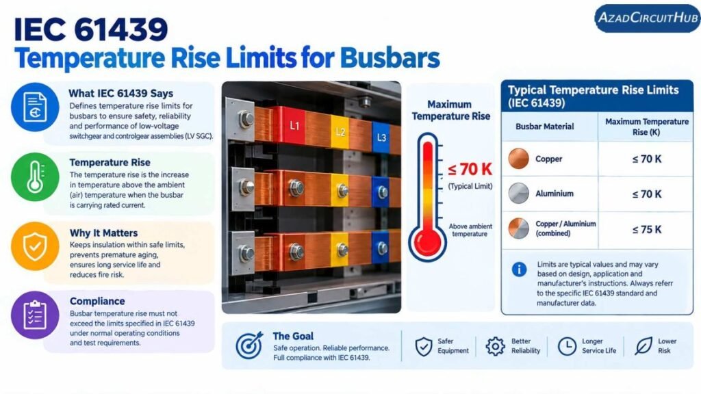
Table of Contents
Table of Contents
IEC 61439 Temperature Rise Limits at a Glance
The following table provides commonly referenced temperature-rise limits from IEC 61439-1 for important parts of a low-voltage assembly. Values are temperature rise above the surrounding ambient air, not the final conductor temperature.
| Assembly Part | Typical IEC 61439 Temperature-Rise Limit |
|---|---|
| Terminals for external insulated conductors | 70 K |
| Accessible external surfaces, metal | 30 K |
| Accessible external surfaces, insulating material | 40 K |
| Manual operating means, metal | 15 K |
| Manual operating means, insulating material | 25 K |
| Busbars and conductors | Depends on component, material, insulation and verification |
| Connections and contacts | Subject to applicable requirements and component limitations |
A kelvin temperature difference has the same numerical size as a Celsius temperature difference. Therefore, a 70 K temperature rise means the component is 70°C hotter than the reference ambient temperature.
For busbar design, the complete assembly must be considered rather than applying one temperature-rise figure to the copper or aluminium bar alone.
If you are sizing a busbar before checking its thermal performance, the Bus Bar Heat Capacity Calculator can provide a useful preliminary estimate of current-carrying capability.
What Does Temperature Rise Mean?
Temperature rise is the difference between the temperature of a component and the ambient air temperature surrounding the assembly.
For example, if the ambient temperature is 35°C and a component has a temperature rise of 50 K:
Final temperature = 35°C + 50°C = 85°C
This distinction is important when interpreting Temperature Rise Limits for Busbars. A temperature rise value is not the same as the maximum operating temperature of the conductor.
Several factors contribute to busbar temperature:
- Load current
- Conductor resistance
- Busbar dimensions
- Copper or aluminium material
- Joint resistance
- Surface area
- Enclosure size
- Ventilation
- Ambient temperature
- Busbar arrangement
- Harmonic currents
- Proximity to other heat-producing components
Why Busbars Heat Up
The main source of busbar heating is electrical power loss caused by resistance.
The basic relationship is:
P = I²R
Where:
- P = power loss in watts
- I = current in amperes
- R = conductor resistance in ohms
This equation shows why a relatively small increase in current can produce a significant increase in heat.
For example, if current increases by 20%, the I² component increases by:
1.2² = 1.44
This represents approximately 44% higher resistive losses, assuming resistance remains constant.
That is why busbar current rating and thermal performance must be checked carefully in high-current switchboards.
IEC 61439 and Busbar Temperature Rise
IEC 61439-1 provides general rules for low-voltage switchgear and controlgear assemblies. It covers construction requirements, service conditions, technical characteristics, and verification requirements.
The standard does not simply provide a universal “busbar temperature limit” that can be applied to every assembly.
Instead, temperature-rise verification considers the actual assembly and its construction. This can involve design verification through testing, comparison with a reference design, or calculation under the permitted verification methods.
| Design Parameter | Effect on Busbar Temperature |
|---|---|
| Higher current | Increases heat generation |
| Larger cross-sectional area | Usually reduces resistance |
| Copper conductor | Generally lower resistance than aluminium for the same area |
| Larger surface area | Improves heat dissipation |
| Enclosed construction | Can reduce natural cooling |
| Forced ventilation | Can improve heat removal |
| Poor joints | Can create local hot spots |
| High ambient temperature | Reduces available thermal margin |
| Close bar spacing | Can affect heat transfer and magnetic effects |
The final verification should follow the applicable IEC 61439 requirements and the assembly manufacturer’s documented design.
Busbar Material and Temperature Rise
Copper and aluminium are widely used for busbars. Their electrical and thermal properties differ, so the same physical dimensions do not necessarily produce the same temperature rise.
| Property | Copper | Aluminium |
|---|---|---|
| Electrical conductivity | Higher | Lower |
| Resistivity | Lower | Higher |
| Density | Higher | Lower |
| Typical busbar use | Compact, high-current assemblies | Lightweight and cost-sensitive designs |
| Joint considerations | Standard bolted connections | Greater attention to joint preparation and compatibility |
Aluminium busbars may require a larger cross-sectional area to achieve a similar electrical performance to copper. Connection design is also important because contact resistance can produce localized heating.
Effect of Busbar Joints
A busbar may have adequate cross-sectional area and still develop excessive local temperature if its joints are poorly designed.
Typical problem areas include:
- Loose bolted connections
- Incorrect torque
- Oxidized contact surfaces
- Poorly prepared aluminium joints
- Inadequate contact area
- Incorrect washers or hardware
- Thermal expansion effects
- Corrosion
A high-resistance joint produces additional heat according to the same basic relationship:
P = I²R
Because the heat is concentrated in a relatively small area, a joint can become much hotter than the surrounding busbar.
Thermal imaging is often useful during commissioning and maintenance because it can identify abnormal temperature differences between similar connections operating under comparable loads.
Ambient Temperature and Busbar Heating
Ambient temperature has a direct effect on the final operating temperature of a busbar.
Consider an assembly operating with a 50 K temperature rise:
| Ambient Temperature | Temperature Rise | Approx. Component Temperature |
|---|---|---|
| 20°C | 50 K | 70°C |
| 25°C | 50 K | 75°C |
| 30°C | 50 K | 80°C |
| 35°C | 50 K | 85°C |
| 40°C | 50 K | 90°C |
The same temperature rise therefore produces a different absolute temperature depending on the surrounding environment.
This is particularly important for electrical panels installed in factories, boiler rooms, outdoor enclosures, solar plants, and other locations with elevated ambient temperatures.
For preliminary conductor selection and heat assessment, the Bus Bar Heat Capacity Calculator can help compare different busbar sizes before detailed IEC verification.
Busbar Enclosure and Ventilation
The enclosure has a major effect on heat dissipation. A busbar installed in an open arrangement can release heat differently from one installed inside a compact metal enclosure.
Important enclosure factors include:
- Internal volume
- Ventilation openings
- Natural convection
- Forced cooling
- Internal component arrangement
- Heat transfer to enclosure walls
- Distance between heat sources
- Installation orientation
A compact switchboard with multiple circuit breakers, contactors, transformers, and busbars may have a significantly different thermal behavior from a simple open busbar arrangement.
Therefore, Temperature Rise Limits for Busbars should always be evaluated as part of the complete assembly.
Practical Busbar Temperature-Rise Checklist
Before finalizing a busbar design, check the following items:
- Determine the continuous design current.
- Select the conductor material.
- Establish the required busbar cross-sectional area.
- Check current density and thermal performance.
- Consider ambient temperature.
- Check enclosure dimensions and ventilation.
- Review busbar spacing and arrangement.
- Design joints with suitable contact area.
- Apply the manufacturer’s specified joint torque.
- Verify the assembly using the applicable IEC 61439 method.
This approach provides a better engineering basis than selecting a busbar solely from a current-density table.
Common Busbar Temperature-Rise Mistakes
Several design mistakes can lead to unexpected heating.
Using Current Density Alone
Current density is useful for preliminary design, but it does not fully represent the thermal behavior of a complete switchboard.
Ignoring Connections
A correctly sized busbar can still experience a hot spot at a poorly made joint.
Using a Fixed Temperature Without Checking Ambient
A 50 K rise at 25°C produces a different final temperature from a 50 K rise at 40°C.
Treating Copper and Aluminium as Identical
Different materials have different resistance, thermal, and mechanical properties. Their joints also require different design considerations.
Assuming More Copper Always Solves the Problem
Increasing cross-sectional area can reduce conductor resistance, but enclosure ventilation, joints, spacing, and other heat sources can still control the final temperature.
Frequently Asked Questions
What is the temperature rise limit for busbars according to IEC 61439?
IEC 61439 does not establish one universal temperature-rise value that applies to every busbar in every assembly. Temperature-rise requirements depend on the component, construction, materials, connections, insulation, and applicable verification method.
What is the maximum temperature of a busbar?
There is no single maximum temperature that applies to every busbar design. The allowable temperature depends on the conductor material, insulation system, connections, surrounding components, ambient conditions, and relevant product requirements.
What does 70 K temperature rise mean?
A 70 K temperature rise means the component temperature is 70°C above the reference ambient temperature. For example, with a 25°C ambient temperature, a 70 K rise corresponds to approximately 95°C.
Does IEC 61439 specify busbar current density?
IEC 61439 should not be reduced to a single universal current-density rule for busbars. Current density can be used during preliminary design, but the completed assembly requires consideration of temperature rise and the applicable verification requirements.
How can busbar temperature rise be reduced?
Temperature rise can generally be reduced by lowering resistance and improving heat dissipation. Larger conductor areas, suitable materials, good-quality joints, appropriate spacing, better ventilation, and suitable enclosure design can all contribute to lower operating temperatures.
Final Considerations
Temperature Rise Limits for Busbars are an important part of designing and verifying low-voltage switchgear assemblies. The key point is that IEC 61439 temperature-rise verification applies to the complete assembly rather than simply assigning one fixed temperature to every busbar.
Current, conductor material, cross-sectional area, joints, enclosure design, ambient temperature, ventilation, and component arrangement all influence thermal performance. A sound design therefore combines preliminary busbar calculations with the required IEC 61439 verification process.
For a quick preliminary assessment of busbar heating and current capacity, the Bus Bar Heat Capacity Calculator can be used alongside the relevant conductor and assembly data.
Get new guides in your feed. Follow Electrical Insights on LinkedIn for new electrical standards guides, calculators and design tips from Azad Circuit Hub.
#IEC61439, #TemperatureRise, #BusbarTemperature, #BusbarSizing, #IECStandards, #ElectricalEngineering, #Switchgear, #LVSwitchgear, #BusbarDesign, #ElectricalSafety