
Functional vs Protective Earthing in Instrumentation
Functional vs Protective Earthing in Instrumentation is an important distinction in industrial automation, process plants, substations, and control systems. Both earthing methods connect electrical equipment or circuits to earth, but they serve different purposes.
Protective earthing is mainly intended to protect people and equipment from electric shock and fault conditions. Functional earthing, on the other hand, is used to help an instrument, signal circuit, communication system, or electronic device operate correctly.
Understanding the difference is especially important when designing PLC panels, DCS systems, SCADA networks, transmitters, control cabinets, and sensitive analog signal circuits.
| Feature | Functional Earthing | Protective Earthing |
|---|---|---|
| Main purpose | Correct operation and signal stability | Electrical safety |
| Primary concern | Noise, reference potential and interference | Shock and fault protection |
| Typical connection | Instrument reference, cable shield or electronic circuit | Equipment enclosure and exposed metalwork |
| Fault-current role | Usually not the primary purpose | Provides a low-impedance fault path |
| Common application | PLC, DCS, instrumentation and communication | Motors, panels, cabinets and metallic enclosures |
| Typical design goal | Stable electrical reference | Automatic fault clearing |
| Also called | FE in many IEC-based systems | PE |
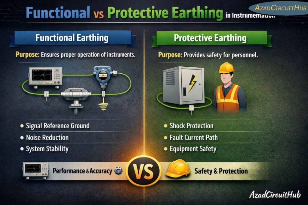
Table of Contents
Table of Contents
What Is Protective Earthing?
Protective earthing connects exposed conductive parts of electrical equipment to the protective earth system. If insulation fails and a live conductor contacts a metal enclosure, the protective conductor provides a suitable path for fault current.
The resulting fault current should operate the appropriate protective device, such as a circuit breaker, fuse, or protective relay.
For example, a metal control cabinet supplied from a low-voltage distribution board should normally have its enclosure bonded to the protective earth conductor. The same principle applies to motor frames, junction boxes, cable trays, metallic equipment structures, and other exposed conductive parts.
The key objective of protective earthing is safety.
| Protective earthing component | Typical function |
|---|---|
| PE conductor | Carries fault current |
| Equipment bonding | Keeps exposed metalwork at a similar potential |
| Main earthing terminal | Connects protective conductors to the earthing system |
| Earth electrode | Provides connection between the installation and soil |
| Protective device | Disconnects the faulty circuit |
Protective earthing should not be confused with simply driving an earth rod into the soil. A complete safety system includes bonding, protective conductors, fault-current paths, and suitable disconnection of the supply.
What Is Functional Earthing?
Functional earthing is used when an electrical or electronic system needs an earth reference to achieve its intended operation.
It can be particularly important in instrumentation because analog signals may be only a few volts, millivolts, or even smaller differential signals. Electrical noise from variable-frequency drives, motors, contactors, transformers, switching power supplies, and high-current cables can interfere with these signals.
A suitable functional earth or reference arrangement can help control unwanted noise and provide a stable reference for electronic circuits.
Functional earthing may be associated with:
- Instrument signal reference
- Electronic circuits
- EMC control
- Cable shields and screens
- Communication systems
- PLC and DCS equipment
- Sensitive measurement equipment
- Surge and transient control arrangements
The exact arrangement depends on the equipment manufacturer’s instructions and the applicable electrical and EMC standards.
Functional vs Protective Earthing in Instrumentation: Key Differences
Functional vs Protective Earthing in Instrumentation becomes easier to understand when the purpose of each connection is considered separately.
Protective earth is fundamentally a safety measure. Functional earth is primarily associated with equipment operation, electromagnetic compatibility, signal integrity, or a defined electrical reference.
| Parameter | Functional Earth | Protective Earth |
|---|---|---|
| Abbreviation | FE | PE |
| Primary objective | Functional performance | Personnel protection |
| Protects against electric shock | Not its primary function | Yes |
| Supports EMC performance | Often | Yes, when correctly designed |
| Carries normal operating current | May, depending on design | Normally should not |
| Used on metal enclosure | Only where specified | Normally required |
| Used for cable shielding | Frequently | Depends on system design |
| Design priority | Signal integrity and equipment operation | Safety and fault protection |
One important point is that FE and PE are not automatically interchangeable. A designer should follow the equipment documentation, project earthing philosophy, and applicable standards rather than assuming that every instrument earth connection can be bonded in the same way.
Why Earthing Matters in Instrumentation
Industrial instrumentation often operates in electrically noisy environments. A transmitter may be installed close to a large motor, while its 4–20 mA signal travels hundreds of meters to a control room.
Without proper bonding, shielding, grounding, and cable routing, the signal can experience unwanted interference.
Common symptoms include:
- Unstable analog readings
- PLC input fluctuations
- Incorrect transmitter values
- Communication errors
- Ground-loop currents
- HMI signal instability
- VFD-related interference
- Unwanted noise on thermocouple signals
- Intermittent instrumentation faults
Good earthing is only one part of the solution. Cable segregation, shield termination, twisted-pair construction, isolation, correct panel layout, and electromagnetic compatibility also have major roles.
For projects where multiple field instruments, junction boxes, marshalling panels, and control cabinets are interconnected, a properly engineered instrument earthing system helps maintain a consistent approach to bonding and signal reference.
Instrument Earthing and Ground Loops
Ground loops are a common concern in instrumentation. They can occur when the same signal circuit has multiple unintended connections to earth at different locations.
The voltage difference between those points can produce circulating current through the signal circuit or cable shield.
For example, consider a 4–20 mA transmitter connected to a control system. If the signal shield is incorrectly grounded at several locations, electrical potential differences may cause unwanted current to flow through the shield.
| Problem | Possible effect |
|---|---|
| Multiple shield connections | Ground-loop noise |
| Poor bonding | Voltage differences between equipment |
| Long parallel power and signal cables | Induced interference |
| Incorrect shield termination | Reduced EMC performance |
| Floating metalwork | Increased noise or safety concerns |
There is no universal rule that every instrument shield must always be grounded at exactly one end. Shielding practices depend on the signal type, frequency, EMC environment, equipment design, and manufacturer’s requirements.
How to Design an Instrument Earthing Arrangement
A good instrumentation earthing design begins by identifying the different earthing functions rather than treating every earth connection as identical.
Start by separating:
- Protective bonding requirements.
- Instrument signal reference requirements.
- Cable shield and screen requirements.
- EMC and high-frequency bonding requirements.
- Surge protection and transient current paths.
- Functional requirements specified by equipment manufacturers.
For a control panel, exposed metallic parts should have an appropriate protective bonding arrangement. Instrument cables should be routed away from high-current power cables where practical, particularly from VFD output cables.
Cable shields should be terminated according to the instrument and control-system design. High-frequency EMC performance may require a different bonding approach from low-frequency signal considerations.
A dedicated instrument earth bar can be used in many industrial installations, but its relationship with the main protective earthing system must be clearly defined. Creating an isolated earth electrode simply for instrumentation is not automatically a better solution and can sometimes create dangerous potential differences.
Functional vs Protective Earthing in Instrumentation for PLC and DCS Systems
PLC and DCS installations contain many electronic circuits that can be sensitive to electrical noise.
The protective earth connection normally protects the cabinet and exposed conductive parts. Functional connections may be required for signal references, communication interfaces, shields, EMC filters, or specific electronic modules.
| Equipment | Typical earthing consideration |
|---|---|
| PLC cabinet | Protective bonding plus manufacturer-specified functional connections |
| DCS cabinet | PE bonding and designated instrument/functional connections |
| Remote I/O | PE and functional requirements depend on module design |
| Field transmitter | Shield/reference arrangement depends on loop design |
| VFD panel | Strong PE and EMC bonding requirements |
| Junction box | Bonding depends on enclosure and system design |
| Communication cabinet | PE plus EMC/shielding considerations |
The manufacturer’s installation instructions should take priority for specific electronic equipment.
If you are designing conductor sizes for the associated bonding network, an earth cable size calculator can help establish a preliminary conductor size before checking the final value against the applicable standard, fault current, disconnection time, installation method, and project requirements.
Common Mistakes in Instrument Earthing
Several mistakes repeatedly appear in industrial instrumentation installations.
Treating FE and PE as the same connection
Although they may ultimately be connected within an engineered system, their functions are different. The design should clearly identify each purpose.
Installing a separate earth rod without engineering review
An independent earth electrode can create potential differences between interconnected equipment. Earthing electrodes should form part of a coordinated earthing system.
Grounding cable shields randomly
Shield termination should follow the signal and EMC design. Randomly connecting shields at both ends or leaving them floating can produce poor results depending on the application.
Ignoring VFD interference
VFDs generate high-frequency common-mode currents and electromagnetic interference. Signal cables should be properly segregated and shielded, while equipment bonding should support EMC performance.
Using undersized bonding conductors
Protective conductors must be selected using the applicable electrical standard and fault conditions. Instrumentation does not eliminate the need for proper protective bonding.
Best Practices for Industrial Instrument Earthing
A reliable installation normally follows these principles:
- Maintain a clear distinction between safety and functional requirements.
- Bond metallic enclosures and exposed conductive parts correctly.
- Follow the PLC, DCS, transmitter, and instrument manufacturer’s instructions.
- Use suitable cable shielding and termination practices.
- Keep instrumentation cables separated from noisy power circuits.
- Provide low-impedance bonding where EMC performance requires it.
- Avoid unnecessary isolated earth electrodes.
- Document all earth bars, bonding links, shields, and reference connections.
- Verify continuity and bonding during commissioning.
- Investigate ground-loop problems systematically rather than adding random earth connections.
For a broader design approach covering field instruments, control panels, shields, earth bars, and bonding practices, see our detailed instrument earthing guide before finalizing the plant earthing philosophy.
Functional vs Protective Earthing in Instrumentation: Quick Summary
| Question | Functional Earthing | Protective Earthing |
|---|---|---|
| Why is it used? | Equipment function and signal integrity | Safety |
| Is it a substitute for PE? | No | No |
| Can it reduce noise? | Often | Can support EMC |
| Is it important for PLC/DCS? | Often | Yes |
| Does it require design consideration? | Yes | Yes |
| Should manufacturer instructions be followed? | Yes | Yes |
The most important lesson from Functional vs Protective Earthing in Instrumentation is that earthing should be designed according to its intended function. Protective earthing provides a safety path for fault conditions, while functional earthing supports the correct operation and electromagnetic performance of instrumentation.
A well-designed system combines protective bonding, functional connections, cable shielding, equipment layout, and appropriate EMC practices. Simply adding more earth connections does not necessarily improve an instrumentation system and may introduce ground-loop or potential-difference problems.
Frequently Asked Questions
1. What is the difference between functional earth and protective earth?
Functional earth is primarily provided to support equipment operation, signal reference, or EMC performance. Protective earth is intended to protect people and equipment by providing a suitable fault-current path and helping protective devices disconnect the supply.
2. Can functional earth and protective earth be connected together?
They may be interconnected at a defined point depending on the system design, equipment construction, and applicable standards. They should not be randomly connected at multiple locations because this can create unwanted circulating currents and interference.
3. Is instrument earth the same as protective earth?
Not necessarily. Instrument earth may refer to a functional or signal-related earthing arrangement, while protective earth is a safety function. The exact terminology and connection method should be confirmed from the project earthing philosophy and equipment documentation.
4. Should instrumentation cable shields be grounded at both ends?
There is no single rule for every application. Shield termination depends on signal type, frequency, EMC environment, equipment design, and manufacturer recommendations. High-frequency EMC requirements can favor bonding methods that differ from low-frequency instrumentation practices.
5. Why is proper earthing important for 4–20 mA signals?
A 4–20 mA loop can be affected by unwanted voltage differences, electromagnetic interference, shielding problems, and ground-loop currents. Correct bonding, cable routing, shielding, and signal isolation help maintain stable and accurate measurements.
Get new guides in your feed. Follow Electrical Insights on LinkedIn for new electrical standards guides, calculators and design tips from Azad Circuit Hub.
#FunctionalEarthing, #ProtectiveEarthing, #InstrumentationEarthing, #ElectricalGrounding, #InstrumentGrounding, #EarthingSystems, #EMC, #IndustrialInstrumentation, #ElectricalEngineering, #ControlSystems
