
Circuit Breaker Contact Resistance
Circuit breaker contact resistance is an important measurement used to assess the condition of the main current-carrying contacts inside a circuit breaker. A low and stable resistance indicates a good electrical connection, while an unusually high reading can point to contact wear, contamination, loose connections, oxidation, or mechanical problems.
Although the resistance of a healthy breaker contact is normally very low, even a small increase can create additional heat when the breaker carries high current. Regular testing helps maintenance teams identify problems before they develop into overheating, nuisance trips, insulation damage, or unexpected equipment failure.
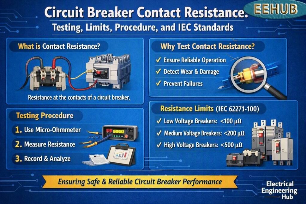
Table of Contents
Table of Contents
| Parameter | Typical consideration |
|---|---|
| Test purpose | Check the condition of current-carrying contacts |
| Measurement | Very low resistance, normally in micro-ohms |
| Common instrument | Micro-ohmmeter or DLRO |
| Test current | Often 50 A to 200 A DC for power breakers |
| Test condition | Breaker isolated, discharged, and properly grounded |
| Key concern | Excessive or unstable resistance |
| Main standards | IEC 62271 series, IEC 60947 series, and applicable manufacturer instructions |
What Is Circuit Breaker Contact Resistance?
Circuit breaker contact resistance is the electrical resistance measured across the closed main contacts of a circuit breaker. The value is usually expressed in micro-ohms (µΩ) because properly functioning power contacts have extremely low resistance.
When a breaker is closed, current flows through its fixed and moving contacts. Every contact interface introduces a small amount of resistance. Under normal conditions, this resistance remains low enough that the resulting voltage drop and heat generation are insignificant.
Over time, however, contact surfaces can deteriorate. Arcing, oxidation, mechanical wear, dirt, inadequate contact pressure, and repeated switching operations can increase resistance.
For example, if a breaker contact develops excessive resistance, the affected pole may become hotter than the other phases while carrying the same load current. Comparing resistance between poles is therefore an important part of preventive maintenance.
Why Is Contact Resistance Testing Important?
The main purpose of this test is to verify the electrical condition of the breaker contacts without dismantling the breaker.
A high resistance reading can indicate:
- Burned or worn contact surfaces
- Oxidation or contamination
- Poor contact pressure
- Loose internal connections
- Damaged flexible connectors
- Mechanical alignment problems
- Incorrect assembly after maintenance
- Deteriorated conductive components
The test also provides a useful baseline for future maintenance. If a breaker previously measured at a low value shows a significant increase during a later inspection, engineers can investigate the change before the condition becomes serious.
For engineers working with testing procedures, the applicable contact resistance test iec standard should always be checked along with the breaker manufacturer’s instructions, because test requirements can vary by breaker type and voltage class.
How Is Circuit Breaker Contact Resistance Measured?
A micro-ohmmeter, also called a ducter or DLRO, is normally used for this measurement. The instrument injects a controlled DC current through the closed breaker contacts and measures the resulting voltage drop.
The resistance is calculated using Ohm’s law:
R = V / I
Where:
- R = resistance in ohms
- V = measured voltage drop
- I = injected test current
Because the resistance is very small, ordinary multimeters are not suitable for accurate breaker contact testing. A four-wire Kelvin measurement is preferred because it minimizes the effect of test-lead and connection resistance.
Basic Test Procedure
- Isolate the circuit breaker from all sources of electrical energy.
- Apply the required safety procedures and verify that the circuit is de-energized.
- Close the breaker so the main contacts are engaged.
- Connect the current leads and potential leads according to the test equipment manufacturer’s instructions.
- Inject the specified DC test current.
- Record the voltage drop and calculated resistance.
- Repeat the measurement for every pole.
- Compare the results with manufacturer data and previous test records.
- Investigate abnormal, unstable, or significantly different readings.
The breaker should remain stationary during the measurement unless the manufacturer’s procedure specifically requires another test method.
Typical Contact Resistance Values
There is no single resistance value that applies to every circuit breaker. The acceptable result depends on the breaker design, current rating, voltage class, contact construction, and manufacturer’s specifications.
As a practical maintenance reference, power circuit breakers often show resistance in the low micro-ohm range.
| Breaker type | Typical range to investigate | Important note |
|---|---|---|
| Low-voltage molded-case breaker | Few to tens of µΩ | Follow manufacturer limits |
| Low-voltage air circuit breaker | Often low µΩ | Compare phases |
| Medium-voltage vacuum breaker | Commonly low µΩ | Manufacturer value is critical |
| Medium-voltage SF6 breaker | Often low µΩ | Check factory/test records |
| High-current power breaker | Very low µΩ expected | Test current and connections matter |
These figures are general engineering references rather than universal pass/fail limits. A breaker with a higher rated current may have a different normal resistance than a smaller device.
Contact Resistance Test Acceptable Value for Breakers
The Contact Resistance Test Acceptable Value for Breakers depends on breaker type, rating, manufacturer specifications, and test current. Low resistance generally indicates clean, properly connected contacts, while a higher or uneven reading can signal oxidation, wear, or loose connections.
| Breaker Type | Typical Contact Resistance |
|---|---|
| Low-voltage breaker | 20–100 µΩ |
| Molded-case circuit breaker | 20–100 µΩ |
| Large power breaker | Usually below 50 µΩ |
Always compare readings with the manufacturer’s limits and previous test results rather than relying on a universal value. For the complete testing method and IEC guidance, see our detailed circuit breaker contact resistance testing guide.
How to Measure Contact Resistance of Circuit Breaker
Measuring breaker contact resistance helps identify loose connections, worn contacts, oxidation, or abnormal heating before a failure occurs. A low-resistance micro-ohmmeter is typically used to inject DC test current through the closed breaker and record the voltage drop.
| Step | Action |
|---|---|
| 1 | Isolate and de-energize the breaker |
| 2 | Close the breaker contacts |
| 3 | Connect the micro-ohmmeter across each pole |
| 4 | Inject the recommended test current |
| 5 | Record and compare resistance readings |
For the complete procedure, test-current guidance, acceptance limits, and applicable IEC requirements, see our detailed guide on How to Measure Contact Resistance of Circuit Breaker.
Factors That Affect Contact Resistance
Several factors can influence the measured value. Temperature is one of the most important because conductor resistance changes with temperature. Test lead connections can also create misleading results if the measurement points are dirty or incorrectly positioned.
Other factors include contact pressure, surface condition, breaker age, mechanical wear, previous fault current, and the condition of internal joints.
A particularly useful diagnostic technique is phase comparison. If two poles show similar readings but one pole is substantially higher, that pole deserves further inspection.
Before performing a test, review the manufacturer’s recommended procedure and the relevant contact resistance test iec standard for the equipment under examination.
How to Interpret Test Results
A single resistance value does not always provide enough information. The result should be considered together with previous measurements, phase-to-phase comparison, breaker specifications, and operating history.
Low and Balanced Readings
Low readings with similar values across all poles generally indicate healthy electrical contact conditions.
One Pole Has Higher Resistance
A significantly higher reading on one phase can suggest localized contact degradation, poor contact pressure, or an internal connection problem.
All Poles Show High Resistance
When every pole produces an unexpectedly high result, first check the test setup, connections, instrument calibration, and test current. A common measurement problem can affect all phases.
Resistance Changes During Testing
An unstable value may indicate poor test connections, contamination, mechanical movement, or a contact surface that is not making consistent electrical contact.
Common Testing Mistakes
Contact resistance testing looks simple, but several errors can reduce the reliability of the results.
Avoid these common mistakes:
- Using a standard digital multimeter
- Testing with insufficient current
- Placing potential leads incorrectly
- Ignoring dirty test connections
- Comparing results without considering temperature
- Treating general reference values as universal limits
- Failing to compare phases
- Ignoring previous maintenance records
- Skipping the manufacturer’s test instructions
For standards-based maintenance programs, reviewing the contact resistance test iec standard before testing can help ensure that the selected method and acceptance criteria match the equipment.
Contact Resistance vs Insulation Resistance
These two tests evaluate different parts of a circuit breaker.
| Test | What it evaluates | Typical instrument |
|---|---|---|
| Contact resistance | Condition of closed main contacts | Micro-ohmmeter |
| Insulation resistance | Insulation between conductors and ground | Insulation resistance tester |
| Timing test | Opening and closing performance | Breaker analyzer |
| High-voltage withstand | Dielectric strength | High-voltage test equipment |
Contact resistance testing focuses on the conductive path, while insulation resistance testing focuses on electrical insulation.
Using both tests provides a more complete picture of breaker condition during commissioning and preventive maintenance.
When Should a Breaker Be Tested?
Testing is commonly performed during commissioning, scheduled preventive maintenance, after major breaker servicing, following a high-current fault, and when thermal or operational abnormalities are observed.
It is also useful when a breaker has been stored for an extended period or when maintenance records indicate a previous abnormal reading.
For a maintenance program, establish a baseline when the breaker is known to be in good condition. Future measurements can then be compared against this reference instead of relying only on generic values.
Frequently Asked Questions
What is a good contact resistance for a circuit breaker?
A good value is normally very low and should be consistent with the manufacturer’s published specification. Many power breakers measure in the low micro-ohm range, but there is no universal value for every breaker.
Can I use a multimeter to measure breaker contact resistance?
A normal multimeter is generally unsuitable because circuit breaker contact resistance is extremely low. A calibrated micro-ohmmeter with a suitable test current and four-wire measurement arrangement is preferred.
What causes high breaker contact resistance?
Common causes include worn contacts, oxidation, contamination, inadequate contact pressure, loose internal joints, mechanical problems, and damage caused by previous fault currents.
How often should circuit breaker contacts be tested?
The interval depends on the breaker type, operating environment, duty cycle, manufacturer recommendations, and maintenance program. Testing is also appropriate after major maintenance or significant fault events.
Which standard covers contact resistance testing?
The applicable standard depends on the type and voltage class of the circuit breaker. IEC 62271 series standards are relevant to high-voltage switchgear and controlgear, while IEC 60947 series standards apply to many low-voltage switchgear devices. Always verify the current edition and the manufacturer’s requirements before testing.
If you are building a broader electrical testing program, review the contact resistance test iec standard alongside the requirements that apply to your specific breaker and installation.
Final Takeaway
Circuit breaker contact resistance testing is a simple but powerful condition-assessment technique. It helps identify deteriorating contacts, poor connections, and abnormal current paths before they cause excessive heating or operational problems.
The most reliable approach is to use a calibrated micro-ohmmeter, follow a four-wire measurement method, compare all poles, maintain historical test records, and evaluate the results against manufacturer specifications. For standards-based work, always confirm the appropriate contact resistance test iec standard and equipment-specific requirements before accepting a test result as satisfactory.
Related Guides & Tools
Get new guides in your feed. Follow Electrical Insights on LinkedIn for new electrical standards guides, calculators and design tips from Azad Circuit Hub.
#CircuitBreaker, #ContactResistance, #ElectricalTesting, #CircuitBreakerTesting, #IECStandards, #ElectricalMaintenance, #MicroOhmTest, #SwitchgearTesting, #BreakerMaintenance, #ElectricalEngineering
