Busbar Contact Resistance
Busbar joints are critical points in electrical power systems. A busbar may carry hundreds or thousands of amperes, but its performance depends on more than the size and material of the conductor. The quality of each bolted, clamped, or flexible connection also matters. A poor connection can create excessive heat, voltage drop, energy loss, and even equipment failure.
Busbar Contact Resistance is the resistance present at the interface between two connected conductive surfaces. It is normally very low, often measured in micro-ohms. Measuring this resistance helps engineers identify loose joints, oxidation, contamination, poor surface preparation, and other connection problems before they develop into serious faults.
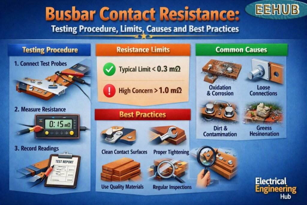
Table of Contents
Table of Contents
What Is Busbar Contact Resistance?
Busbar Contact Resistance is the electrical resistance across a busbar connection or joint. Unlike the resistance of the copper or aluminum bar itself, contact resistance mainly comes from the small interface where two conductive surfaces meet.
Even when two metal surfaces appear flat and smooth, they actually touch at microscopic points. Oxide layers, dirt, surface roughness, insufficient contact pressure, and incorrect torque can reduce the effective contact area.
A high reading can indicate that a joint is not making adequate electrical contact.
Common busbar connections include:
- Copper-to-copper joints
- Aluminum-to-aluminum joints
- Copper-to-aluminum connections
- Busbar-to-breaker connections
- Busbar-to-disconnector connections
- Transformer and switchgear busbar joints
- Flexible busbar links
For a broader explanation of accepted testing practices, see our Contact Resistance Test IEC Standard guide.
Why Is Low Contact Resistance Important?
A good busbar joint should provide a stable, low-resistance electrical path. When resistance increases, the connection generates additional heat according to the relationship:
P = I²R
Here, P is heat loss, I is current, and R is resistance.
The effect becomes significant at high current. For example, a resistance of only 100 micro-ohms at 1,000 A produces:
P = (1,000)² × 0.0001 = 100 W
That means a tiny resistance at one joint can produce substantial localized heating.
Excessive heating can cause:
- Insulation deterioration
- Busbar discoloration
- Joint loosening
- Oxidation
- Thermal expansion
- Increased resistance
- Hot spots
- Equipment damage
- Fire risk in severe cases
This is why contact resistance measurement is an important part of switchgear and busbar maintenance.
IEC Standard for Busbar Contact Resistance
What IEC Standards Say About Busbar Contact Resistance
IEC standards provide guidance for verifying electrical connections, temperature rise, and performance of busbar assemblies. The acceptable resistance depends on the equipment design, joint type, contact area, and manufacturer specifications.
| Test Point | What to Check |
|---|---|
| Busbar joint | Low and stable resistance |
| Contact surface | Clean and properly tightened |
| Test current | Suitable for the joint and test instrument |
| Final result | Compare with manufacturer limits |
When testing Busbar Contact Resistance, always record the measured value and compare it with the applicable equipment documentation.
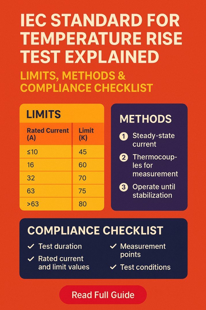
For the complete testing procedure, recommended limits, causes of high resistance, and practical testing methods, see this detailed guide to IEC Standard for Busbar Contact Resistance.
Busbar Contact Resistance Test
A proper Busbar Contact Resistance Test helps identify loose joints, oxidation, contamination, and poor connections before they create excessive heating. Using a micro-ohmmeter, technicians measure the resistance across each busbar joint and compare results with expected values.
| Test Item | Typical Check |
|---|---|
| Test instrument | Micro-ohmmeter |
| Connection | Across the joint |
| Main concern | Excessive resistance |
| Follow-up | Clean, tighten, or replace |
Low and consistent readings generally indicate a healthy connection, while an unusually high or uneven value deserves investigation.
For the complete testing procedure, acceptable readings, causes of high resistance, and practical testing tips, see our detailed guide to Busbar Contact Resistance Test. Regular testing is especially useful during commissioning, preventive maintenance, and after major electrical equipment work.
Typical Values and Acceptance Criteria
There is no single universal resistance value that applies to every busbar joint. The acceptable result depends on the equipment manufacturer’s specifications, joint design, conductor material, current rating, connection type, and applicable standard.
In practical maintenance work, readings are commonly evaluated in micro-ohms and compared with the manufacturer’s baseline or previous test results.
| Connection condition | Typical interpretation |
|---|---|
| Very low and stable reading | Good electrical connection |
| Slightly higher than previous result | Monitor and investigate |
| Significantly higher than comparable joints | Possible connection problem |
| Rapid increase from historical value | Requires investigation |
| Very high or unstable reading | Possible loose, contaminated, or damaged joint |
For formal testing, always use the equipment manufacturer’s limits and the applicable project or maintenance specification rather than relying on a generic number.
How to Measure Busbar Contact Resistance
A low-resistance ohmmeter, commonly called a DLRO or micro-ohmmeter, is normally used for this test.
The instrument applies a relatively high test current through the joint and measures the voltage drop across the connection. Using Ohm’s law, the instrument calculates the resistance.
The basic relationship is:
R = V / I
Because the resistance is extremely small, a four-wire Kelvin measurement is preferred. Two leads carry the test current, while two separate sensing leads measure the voltage directly across the joint.
Basic Testing Procedure
Follow the equipment manufacturer’s procedure and site safety requirements before starting.
- Isolate the electrical equipment from all energized sources.
- Apply the required lockout/tagout procedure.
- Verify that the busbar is de-energized.
- Confirm that the test area is safe and properly grounded as required.
- Connect the current leads on opposite sides of the joint.
- Connect the potential leads close to the joint being tested.
- Select the appropriate test current.
- Apply the test current and allow the reading to stabilize.
- Record the measured resistance.
- Compare the result with specifications and previous readings.
- Repeat the measurement if the result appears abnormal.
- Restore the equipment according to the approved commissioning or maintenance procedure.
The exact test current depends on the instrument, equipment, and testing standard. Never assume that a particular current is suitable for every busbar system.
Factors That Increase Contact Resistance
Several conditions can increase the resistance of a busbar joint.
Loose Bolted Connections
Insufficient tightening reduces contact pressure between the conductive surfaces. Thermal cycling and vibration can make the problem worse over time.
Oxidation and Corrosion
Aluminum develops an oxide layer naturally, while copper can also develop surface oxidation. Contamination or corrosion at the joint can increase resistance.
Poor Surface Preparation
Paint, grease, dirt, moisture, oxide, and other unwanted materials can prevent proper metal-to-metal contact.
Incorrect Torque
Over-tightening can damage components, while under-tightening may produce inadequate contact pressure. Use the manufacturer’s specified torque and an appropriate calibrated torque wrench.
Thermal Cycling
Repeated heating and cooling can cause expansion and contraction. Over time, this may affect the mechanical integrity of a connection.
Dissimilar Metals
Copper-to-aluminum joints require suitable joint design and compatible hardware. Improper connections can suffer from oxidation, galvanic corrosion, and increased resistance.
What Causes High Busbar Contact Resistance?
When a test result is higher than expected, inspect the physical connection before assuming the measuring instrument is faulty.
| Possible cause | What to inspect |
|---|---|
| Loose connection | Bolt condition and torque |
| Oxidation | Surface condition |
| Corrosion | Joint and hardware |
| Contamination | Dirt, grease, paint, moisture |
| Poor alignment | Busbar mating surfaces |
| Damaged hardware | Washers, bolts, clamps |
| Uneven pressure | Joint assembly |
| Incorrect joint compound | Manufacturer requirements |
| Instrument issue | Leads, connections, calibration |
A useful maintenance practice is to compare similar joints under similar conditions. A single unusually high reading can be more meaningful than simply comparing a result with a generic limit.
For a deeper explanation of measurement methods and standards, use our Contact Resistance Test IEC Standard resource.
Best Practices for Accurate Testing
Accurate low-resistance testing requires careful preparation. Before taking measurements, inspect the test leads and clean their contact points. Keep potential leads close to the joint so the measurement represents the intended connection.
Avoid placing voltage-sensing leads across unnecessary sections of the busbar because this can affect the measured value.
Other useful practices include:
- Use a calibrated micro-ohmmeter.
- Follow the manufacturer’s recommended test current.
- Use the four-wire Kelvin method.
- Keep test lead connections clean and secure.
- Record temperature and test conditions where required.
- Compare readings with previous maintenance records.
- Test similar joints for comparison.
- Investigate sudden changes rather than relying only on absolute values.
- Follow the applicable safety and maintenance procedure.
Busbar Contact Resistance Test Report
A proper test report should make future comparison easy. At minimum, record the equipment identification, joint location, test current, measured resistance, test date, instrument details, and technician information.
| Test record | Example information |
|---|---|
| Equipment | Main LV switchboard |
| Joint | Phase A busbar joint |
| Material | Copper |
| Test method | Four-wire Kelvin |
| Test current | As specified by procedure |
| Resistance | Measured micro-ohm value |
| Ambient temperature | Recorded value |
| Instrument | Micro-ohmmeter model |
| Result | Pass/Investigate |
| Remarks | Physical inspection findings |
Historical records are especially valuable because they allow maintenance teams to identify gradual deterioration.
When Should Busbar Joints Be Tested?
Testing is commonly performed during commissioning, preventive maintenance, major shutdowns, and after modifications or repairs.
It may also be appropriate when thermographic inspection identifies a hot spot, when a joint has been disturbed, or when previous measurements show an increasing resistance trend.
Combining micro-ohm testing with visual inspection and infrared thermography provides a stronger condition assessment than using one method alone.
Final Takeaway
Busbar Contact Resistance is a small electrical value with potentially large consequences. A poor connection can produce significant heat when high current flows through it, making early detection important for switchboards, substations, motor control centers, transformers, and other high-current equipment.
The most reliable approach is to use a calibrated low-resistance ohmmeter, follow a four-wire measurement technique, maintain consistent test conditions, and compare results with manufacturer specifications and historical measurements. Physical inspection should also be performed whenever an abnormal reading is found.
If you are developing a complete electrical maintenance testing program, our Contact Resistance Test IEC Standard guide can help you understand the relevant testing principles, methods, and acceptance considerations.
FAQs About Busbar Contact Resistance
1. What is a good busbar contact resistance?
There is no single value that applies to every busbar connection. A good result is normally a low and stable reading that meets the manufacturer’s specification and is consistent with comparable joints and previous test results.
2. What instrument is used to measure busbar joint resistance?
A micro-ohmmeter, also known as a DLRO, is commonly used. A four-wire Kelvin connection provides accurate measurements by separating the current path from the voltage measurement path.
3. Why is busbar contact resistance measured in micro-ohms?
Busbar connections are designed to have extremely low resistance. Measuring them in micro-ohms provides the resolution needed to identify small changes that could become significant at high operating currents.
4. What causes high resistance in a busbar joint?
Common causes include loose bolts, oxidation, corrosion, contamination, inadequate contact pressure, poor surface preparation, damaged hardware, misalignment, and unsuitable connections between dissimilar metals.
5. How often should busbar contact resistance be tested?
The interval depends on the equipment, manufacturer recommendations, operating conditions, maintenance program, and applicable standards. Testing is often performed during commissioning and scheduled preventive maintenance, with additional testing after major repairs or when abnormal heating is detected.
Related Guides & Tools
Get new guides in your feed. Follow Electrical Insights on LinkedIn for new electrical standards guides, calculators and design tips from Azad Circuit Hub.
#BusbarContactResistance, #ContactResistance, #BusbarTesting, #ElectricalTesting, #ElectricalMaintenance, #SwitchgearTesting, #PowerSystems, #ElectricalEngineering, #PreventiveMaintenance, #IECStandards