Contact Resistance Test Acceptable Value for Breakers: IEC 62271-100
Contact resistance is a key indicator of breaker health. A high reading can point to worn contacts, loose joints, oxidation, contamination, or poor connections. This guide explains the Contact Resistance Test Acceptable Value for Breakers, with practical limits, test methods, breaker-type comparisons, and IEC 62271-100 considerations.
| Breaker Type | Typical Contact Resistance | Common Test Current | Main Standard Reference |
|---|---|---|---|
| ACB | Usually below 100 µΩ | 100 A or higher | IEC 60947-2 |
| VCB | Usually below 100 µΩ | 50–200 A | IEC 62271-100 |
| MCCB | Typically 20–200 µΩ | 10–100 A | IEC 60947-2 |
| Oil Circuit Breaker | Often below 100–150 µΩ | 100 A or higher | Applicable legacy/project standard |
| MV/HV Breaker | Manufacturer-specific | 50–200 A or higher | IEC 62271 series |
Important: There is no single universal resistance value that applies to every breaker. The manufacturer’s factory or commissioning data and the applicable product standard should take priority.
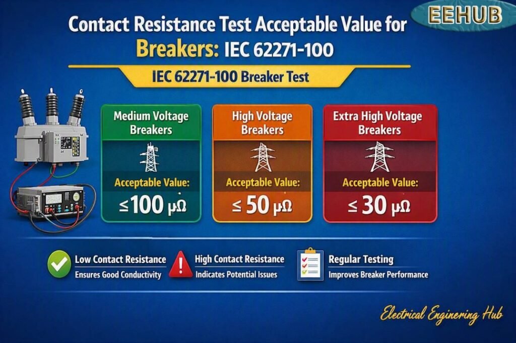
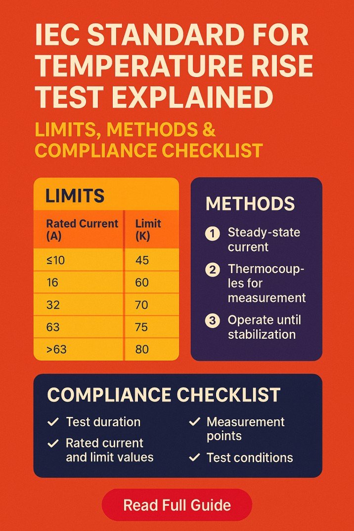
Table of Contents
Table of Contents
What Is Breaker Contact Resistance?
Breaker contact resistance is the electrical resistance measured across the closed main contacts of a circuit breaker. It is normally very low because the contacts must carry rated current with minimal power loss and heating.
The measurement is generally expressed in micro-ohms (µΩ). A four-wire micro-ohmmeter, also called a ducter or contact resistance tester, is commonly used because ordinary multimeters cannot accurately measure such low resistance.
A good contact system should provide:
- Low electrical resistance
- Stable current-carrying performance
- Minimal temperature rise
- Reliable operation under load
- Good mechanical contact pressure
- Consistent readings between phases
For engineers and maintenance teams, trending the resistance over time is often more useful than relying on one fixed pass/fail number.
Need a complete guide to test methods and standards? Read our Circuit Breaker Contact Resistance guide for a broader explanation of testing, limits, procedures, and IEC requirements.
Contact Resistance Test Acceptable Value for Breakers
The acceptable value depends on the breaker design, current rating, contact arrangement, manufacturer, and test procedure.
For many low-voltage and medium-voltage breakers, readings in the tens of micro-ohms are considered very good. Values approaching or exceeding 100 µΩ may require closer investigation, particularly when the manufacturer’s recommended value is lower.
A useful field approach is to compare:
- Each phase against the other phases.
- The measured value against the manufacturer’s factory data.
- The current reading against previous maintenance results.
- The result against the applicable standard and test specification.
| Test Result | General Interpretation | Recommended Action |
|---|---|---|
| Very low and balanced | Excellent contact condition | Accept and record |
| Low but slightly different between phases | Usually acceptable | Monitor trend |
| Noticeably higher than other phases | Possible contact or connection issue | Investigate |
| High resistance with rising trend | Possible degradation | Inspect and retest |
| Extremely high or unstable | Poor contact, loose joint, contamination, or damaged mechanism | Remove from service if safety assessment requires |
These ranges are practical guidance rather than universal acceptance limits.
IEC 62271-100 and Contact Resistance Testing
IEC 62271-100 applies to AC circuit breakers used in high-voltage switchgear and controlgear. It covers requirements and testing for circuit breakers, including their electrical and mechanical performance.
It is important to understand that IEC 62271-100 does not simply provide one universal field-service value such as “below 100 µΩ = pass” for every breaker.
The actual acceptance criteria can depend on the breaker design, rated current, construction, manufacturer specifications, and applicable type and routine test requirements.
For maintenance work, the manufacturer’s instructions should therefore be used together with the relevant IEC requirements and the project’s commissioning or maintenance specification.
Breaker-Type Acceptable-Value Comparison
Different breaker technologies can produce different resistance readings. The following table provides practical field reference ranges, not mandatory IEC pass/fail limits.
| Breaker Type | Typical Practical Range | Value Requiring Investigation | Important Consideration |
|---|---|---|---|
| ACB | 20–100 µΩ | >100 µΩ or abnormal phase difference | Check main contacts and bolted joints |
| VCB | 20–100 µΩ | >100 µΩ or significant phase variation | Compare with OEM test data |
| MCCB | 20–200 µΩ | High compared with OEM data or other poles | Resistance varies with frame and contact design |
| Oil Breaker | 30–150 µΩ | >150 µΩ or rising trend | Inspect contacts and connections |
| MV/HV Breaker | Manufacturer-specific | Significant deviation from baseline | OEM limits should take priority |
A breaker with a 70 µΩ reading may be acceptable in one application but unacceptable in another. The same reading should not automatically be treated as a universal pass value.
How Is Contact Resistance Measured?
A micro-ohmmeter sends a controlled DC test current through the closed breaker contacts while measuring the voltage drop across them.
The resistance is calculated using Ohm’s law:
R = V / I
Where:
- R = contact resistance
- V = measured voltage drop
- I = injected test current
For example, if a tester injects 100 A and measures a 5 mV voltage drop:
R = 0.005 / 100 = 0.00005 Ω = 50 µΩ
This is why a high-current, four-wire measurement is preferred. The separate current and voltage leads reduce the influence of lead resistance and improve measurement accuracy.
Recommended Contact Resistance Test Procedure
A proper test should follow the breaker manufacturer’s instructions and site safety procedure.
1. Isolate the breaker
De-energize and isolate the equipment. Apply the required lockout/tagout procedure and verify that the circuit is safe to work on.
2. Close the breaker
The main contacts must normally be closed during the measurement. Follow the manufacturer’s instructions for operating the breaker.
3. Connect the test leads
Place the current leads on each side of the current path and the potential leads as close as practical to the contact interfaces.
4. Select the test current
Use the manufacturer’s specified test current. High-current micro-ohm testing is common for power circuit breakers.
5. Record each pole
Measure all phases separately and record the resistance in micro-ohms.
6. Compare the results
Compare the readings with OEM data, previous maintenance records, and the other phases.
7. Investigate abnormal readings
If one phase is substantially higher, inspect the contacts, terminals, flexible connectors, busbar joints, and operating mechanism as applicable.
For a step-by-step explanation of the complete measurement process, see our Circuit Breaker Contact Resistance resource before performing field testing.
What Causes High Breaker Contact Resistance?
Several conditions can increase contact resistance.
Contact Wear
Repeated fault interruption and normal switching can gradually wear the contact surfaces. Excessive wear can reduce the effective contact area.
Oxidation and Contamination
Dust, oxidation, moisture, and other contaminants can increase resistance at contact interfaces.
Loose Connections
Loose terminal or busbar connections can create additional resistance and localized heating.
Incorrect Contact Pressure
A breaker mechanism that does not provide adequate contact pressure can result in poor electrical contact.
Contact Misalignment
Misaligned contacts may touch over a smaller area than intended, increasing resistance.
Damaged Flexible Connections
Flexible copper connectors and internal current paths can deteriorate due to mechanical movement, overheating, or repeated operation.
Why Phase-to-Phase Comparison Matters
Phase comparison is one of the quickest ways to identify an abnormal condition.
For example:
| Phase | Measured Resistance |
|---|---|
| L1 | 42 µΩ |
| L2 | 45 µΩ |
| L3 | 43 µΩ |
These readings are closely grouped.
Now consider:
| Phase | Measured Resistance |
|---|---|
| L1 | 41 µΩ |
| L2 | 44 µΩ |
| L3 | 118 µΩ |
The third phase deserves investigation even if a generic 100 µΩ value is not being used as a formal acceptance criterion.
A large difference between poles can be more meaningful than the absolute number alone.
Contact Resistance Test Acceptance Criteria
When determining whether a breaker passes, use a hierarchy of evidence.
First: Check the manufacturer’s specified resistance or acceptance range.
Second: Compare the result with the original factory or commissioning measurement.
Third: Compare all phases for consistency.
Fourth: Review historical maintenance results for an increasing trend.
Fifth: Apply the requirements of the applicable IEC, project, and site maintenance specification.
This approach prevents technicians from rejecting a healthy breaker simply because its resistance differs from an arbitrary internet value.
What Should You Do If Resistance Is Too High?
A high reading should not automatically lead to breaker replacement.
Start by confirming the test setup. Check that the leads are correctly positioned, the test current is appropriate, and the connections are clean and secure.
If the result remains high:
- Repeat the measurement.
- Compare all phases.
- Check terminal connections.
- Inspect accessible contact surfaces.
- Check for oxidation or contamination.
- Review breaker operation and contact wear.
- Compare against OEM limits.
- Perform additional diagnostic tests if required.
After corrective maintenance, repeat the contact resistance measurement and document the final readings.
Contact Resistance and Temperature Rise
High resistance produces additional heat when current flows through the breaker.
The approximate power loss can be expressed as:
P = I²R
This relationship is important because heating increases rapidly with current.
For example, at 1,000 A and 100 µΩ:
P = 1,000² × 0.0001 = 100 W
That heat is concentrated at the contact or connection area. Excessive localized heating can accelerate contact degradation and eventually cause insulation or equipment damage.
This is why contact resistance testing is an important part of preventive maintenance.
For related testing guidance, visit our Circuit Breaker Contact Resistance hub to understand acceptable readings, testing equipment, IEC standards, and troubleshooting methods.
Best Practices for Accurate Results
Use these practices to improve repeatability:
- Use a calibrated micro-ohmmeter.
- Follow the test equipment manufacturer’s instructions.
- Use a four-wire Kelvin connection.
- Apply the specified test current.
- Clean and secure test points.
- Keep test conditions consistent.
- Test every pole separately.
- Record ambient and equipment conditions when relevant.
- Compare results with previous measurements.
- Follow OEM and applicable IEC requirements.
Avoid using a standard digital multimeter to make a final decision on circuit breaker contact resistance. Its lead and contact resistance can be much greater than the resistance being measured.
Frequently Asked Questions
What is an acceptable contact resistance for a circuit breaker?
There is no universal value for every breaker. Many breakers show readings below 100 µΩ, but the acceptable limit depends on the breaker design, rating, manufacturer, and applicable standard. OEM data should be the primary reference.
What is the typical VCB contact resistance?
Many vacuum circuit breakers have contact resistance in the tens of micro-ohms and often below 100 µΩ. However, the manufacturer’s factory and maintenance specifications should determine the actual acceptance limit.
What happens if breaker contact resistance is high?
High resistance causes additional I²R heating and voltage drop. It may indicate worn contacts, contamination, oxidation, loose connections, poor contact pressure, or another defect. The breaker should be investigated before returning it to service when the result exceeds its specified limit.
What test current is used for contact resistance?
The test current depends on the breaker and test standard. High-current DC testing, commonly 50 A, 100 A, or 200 A, is used for many power circuit breakers. Always follow the manufacturer’s recommended procedure.
Does IEC 62271-100 specify a single contact resistance limit?
No. IEC 62271-100 should not be interpreted as providing one universal field acceptance value for every circuit breaker. The applicable breaker requirements, manufacturer data, test specifications, and commissioning criteria must be considered together.
Final Takeaway
The Contact Resistance Test Acceptable Value for Breakers should never be judged from one generic number alone. Values below 100 µΩ are common in many applications, but the correct acceptance limit depends on breaker type, rated current, construction, manufacturer data, and applicable testing requirements.
IEC 62271-100 is particularly relevant to high-voltage AC circuit breakers, while low-voltage breakers such as many ACBs and MCCBs fall under the IEC 60947 series. For reliable maintenance decisions, use calibrated test equipment, compare all phases, review historical trends, and always give OEM specifications priority.
A good contact resistance test is not just about obtaining a low number. It is about confirming that the breaker has a stable, balanced, and reliable current path.
Related Guides & Tools
Get new guides in your feed. Follow Electrical Insights on LinkedIn for new electrical standards guides, calculators and design tips from Azad Circuit Hub.
#ContactResistanceTest, #BreakerTesting, #IEC62271100, #CircuitBreakerTesting, #BreakerContactResistance, #ElectricalTesting, #HighVoltageTesting, #IECStandards, #CircuitBreakerMaintenance, #ElectricalEngineering