Altitude Correction Factor Clearance Calculator: Formula, Table and Examples
An altitude correction factor clearance calculator helps electrical engineers determine the increased air clearance required when electrical equipment operates above sea level. At higher altitudes, air density decreases, reducing its dielectric strength. As a result, the same physical clearance may not provide the same insulation performance as it does at sea level.
This calculation is important for substations, switchgear, transformers, overhead busbars, and medium-voltage equipment. Engineers must consider rated voltage, standard insulation levels, minimum air clearance, and the applicable IEC or NEC requirements before approving an installation.
Altitude Correction Factor Clearance Calculator Reference Table
The following table provides indicative altitude correction factors using the commonly applied IEC 60071-2 relationship for external insulation. Confirm the applicable edition and equipment requirements before using these values for design.
| Altitude Above Sea Level | Approx. Air Density Correction Factor | Clearance Multiplier |
|---|---|---|
| 1,000 m | 1.11 | 1.11 |
| 1,500 m | 1.18 | 1.18 |
| 2,000 m | 1.25 | 1.25 |
| 2,500 m | 1.33 | 1.33 |
| 3,000 m | 1.42 | 1.42 |
| 3,500 m | 1.51 | 1.51 |
| 4,000 m | 1.62 | 1.62 |
| 4,500 m | 1.73 | 1.73 |
| 5,000 m | 1.86 | 1.86 |
These factors are approximate and assume the commonly used relationship.
Ka = e^[m × (H − 1000) / 8150]
The correct exponent and reference conditions depend on the insulation coordination method and standard being applied. Do not apply this table blindly to every type of insulation.
Altitude Correction Factor Clearance Calculator
Find the altitude correction factor for air insulation and the increased electrical clearance needed at your site elevation. Choose a method, enter your sea-level clearance, and compare the result against existing installed clearances.
How to Use
- Pick a standard voltage class from the list to load a typical sea-level withstand level and minimum clearance, or select Custom and type your own values.
- Enter the site altitude and choose meters or feet.
- Select the calculation method and the withstand type. Lightning impulse and power-frequency withstand use the full altitude effect; switching impulse uses a reduced effect.
- Optionally add a design margin and the clearance you currently have installed.
- Press Calculate. Read the corrected clearance, the equivalent sea-level withstand to specify, the comparison bars and the altitude reference table.
Inputs
Results
Correction Factor and Clearance by Altitude
Uses the method, withstand type, clearance, margin and temperature entered above. The highlighted row is your site altitude.
| Altitude (m) | Altitude (ft) | Correction factor | Corrected clearance (mm) | Increase (%) |
|---|
Technical Notes
Why altitude matters. Air gets thinner as elevation rises. Thinner air has fewer molecules to resist a spark, so the same gap that is safe at sea level can flash over at a mountain site. Designers compensate by widening air clearances or by specifying equipment with a higher sea-level withstand rating.
Exponential method. The IEC approach applies a smooth increase of the correction with height and is the most widely used in substation design. It works for external insulation and air gaps and is scaled by an exponent that depends on the type of voltage stress.
Air density method. This approach calculates the actual air pressure at your altitude, adjusts it for the site temperature, and relates it to standard laboratory conditions. Hot sites are slightly worse than cold sites at the same elevation, which this method captures.
IEEE/ANSI table method. North American switchgear and transformer standards state that no correction is needed up to 1000 meters and publish stepped factors above that. This tool interpolates between the published steps. Use it when your specification is written to those standards.
Withstand type. Lightning impulse and short-duration power-frequency stresses are corrected in full. Switching impulse stresses on large air gaps respond less to air density, so a lower exponent applies. Your equipment specification or the standard gives the right value for the voltage level.
Equivalent sea-level withstand. If you buy standard equipment tested at sea level, the withstand rating you need on the nameplate is the site requirement multiplied by the correction. This result tells you what to ask the manufacturer for.
Design margin. Many utilities add a small margin for construction tolerance, conductor sag, wind swing and ageing. Enter it as a percentage and it is applied on top of the corrected value.
Limits. Very high altitude, heavy pollution, rain, ice and humidity all change real-world flashover behavior. Internal insulation in sealed or oil-filled equipment is not affected in the same way as air gaps.
What Is an Altitude Correction Factor?
An altitude correction factor compensates for reduced air insulation strength at elevations above the reference altitude. At sea level, air pressure and density are higher. As altitude increases, the reduced air density can make electrical breakdown more likely across an air gap.
For outdoor substations and air-insulated switchgear, engineers may need to increase the clearance between live conductors and grounded metalwork. The required increase depends on the equipment's insulation characteristics and the applicable design standard.
An altitude correction factor clearance calculator provides a practical way to estimate the adjusted clearance before checking the final design against the manufacturer's specifications.
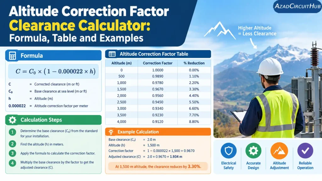
Altitude Correction Factor Formula
A commonly used atmospheric correction relationship for external insulation is:
Ka = e^[m × (H − 1000) / 8150]
Where:
- Ka = altitude correction factor
- e = mathematical constant, approximately 2.71828
- m = exponent determined by the applicable insulation coordination method
- H = installation altitude in metres above sea level
- 1000 = reference altitude in metres
- 8150 = commonly used atmospheric scale-height constant in metres
For a preliminary calculation, an engineer may use m = 1 where justified by the applicable method. The exponent should not be assumed universally for all equipment or insulation conditions.
The corrected clearance can then be estimated as:
C₂ = C₁ × Ka
Where:
- C₂ = corrected clearance at the installation altitude
- C₁ = reference clearance
- Ka = applicable altitude correction factor
This simple multiplication is appropriate only when the selected standard or engineering method permits clearance scaling by the calculated factor. Some insulation coordination procedures require a different relationship or equipment-specific correction.
How to Use an Altitude Correction Factor Clearance Calculator
Follow these technical steps to calculate a preliminary clearance adjustment.
- Identify the installation altitude. Obtain the site's elevation above mean sea level from project drawings, survey data, or verified site information.
- Determine the reference clearance. Identify the minimum air clearance specified for the equipment at the reference altitude. Use the applicable insulation coordination standard, equipment rating, and manufacturer documentation.
- Calculate the altitude factor. Apply the approved atmospheric correction formula using the actual installation altitude and the appropriate exponent.
- Calculate the adjusted clearance. Multiply the reference clearance by the factor if this correction method applies to the equipment.
- Check the final design. Verify phase-to-phase and phase-to-earth clearances, insulation withstand requirements, and the manufacturer's altitude limits.
For example, consider a reference clearance of 300 mm at an altitude of 3,000 m. Using the illustrative factor of 1.42:
C₂ = 300 × 1.42
C₂ = 426 mm
The preliminary adjusted clearance is approximately 426 mm. This result is not an automatic design approval; the required clearance must be verified against the applicable insulation coordination standard and equipment documentation.
Altitude Correction Factors for Substations and Switchgear
Different equipment types may require different treatment. The following table shows where altitude assessment is commonly relevant.
| Equipment | Clearance or Insulation Concern | Required Check |
|---|---|---|
| 11 kV switchgear | Phase-to-phase and phase-to-earth insulation | Manufacturer's altitude rating and applicable standard |
| Outdoor substations | Busbar and conductor air gaps | Insulation coordination and minimum clearances |
| Power transformers | External bushings and terminals | Bushing rating and manufacturer's altitude limits |
| Circuit breakers | External insulation and terminal spacing | Rated withstand levels and installation conditions |
| Overhead busbars | Air clearance to adjacent phases and earth | Applicable electrical design requirements |
| Control panels | Air clearance and creepage distance | Insulation coordination requirements for the assembly |
For an 11 kV installation, consult the relevant 11kv phase to phase clearance reference before finalizing busbar spacing. Nominal system voltage alone does not determine every required clearance; maximum voltage, impulse withstand level, insulation arrangement, and equipment construction also matter.
Altitude Correction vs. Phase Clearance and Creepage Distance
Air clearance and creepage distance are different measurements. Air clearance is the shortest distance through air between conductive parts. Creepage distance is the shortest distance along an insulating surface between conductive parts.
Altitude correction primarily addresses the effect of reduced air density on external insulation. Creepage distance is generally assessed against pollution severity, material properties, and the relevant insulation coordination requirements.
| Parameter | Main Purpose | Altitude Consideration |
|---|---|---|
| Air clearance | Prevent flashover through air | Atmospheric correction may be required |
| Creepage distance | Reduce surface leakage and flashover risk | Pollution and material conditions are key |
| Phase-to-phase clearance | Insulation between energized phases | Check altitude and withstand requirements |
| Phase-to-earth clearance | Insulation between live parts and grounded structures | Check altitude and withstand requirements |
For installations designed under North American requirements, review phase to phase clearance nec alongside the relevant equipment standards. For low-voltage insulation coordination, consult clearance and creepage distance table iec 60664 and verify the applicable scope and edition.
Common Mistakes in Altitude Clearance Calculations
Avoid these common engineering errors:
- Using nominal voltage alone to determine the reference clearance.
- Applying an altitude factor to creepage distance without a supporting standard.
- Assuming all equipment uses the same correction exponent.
- Ignoring the manufacturer's maximum installation altitude.
- Treating a calculated result as a substitute for dielectric withstand verification.
- Using an uncorrected reference clearance from a different insulation coordination standard.
Correct clearance design must account for the equipment's rated insulation level, environmental conditions, installation arrangement, and applicable standards.
Frequently Asked Questions
1. What is the altitude correction factor for electrical clearance?
It is a factor used in an applicable insulation coordination method to account for the effect of altitude on external insulation. Its value depends on installation elevation and the method specified by the relevant standard.
2. How do you calculate clearance at 2,000 metres?
Determine the approved reference clearance and calculate the applicable altitude factor. Using the illustrative factor of 1.25, a 200 mm reference clearance becomes 250 mm. Confirm that the chosen correction method is valid for the equipment.
3. Does altitude affect creepage distance?
Altitude primarily affects insulation through air because air density decreases with elevation. Creepage distance is mainly determined by pollution conditions, insulating material, and the applicable standard. Do not automatically apply the air-clearance factor to creepage distance.
4. At what altitude is electrical equipment derating required?
Many equipment specifications use 1,000 m as a reference altitude, but the actual threshold depends on the product standard and manufacturer. Above the specified limit, insulation, cooling, or other performance characteristics may require assessment.
5. Which standard covers altitude correction for electrical clearance?
IEC 60071-2 addresses application guidelines for insulation coordination, including atmospheric correction considerations for external insulation. IEC 60664-1 covers insulation coordination for equipment within its defined low-voltage scope. Always check the applicable edition and the specific equipment standard.
Conclusion
An altitude correction factor clearance calculator is useful for preliminary insulation coordination in high-altitude substations, switchgear installations, and power distribution systems. The engineer should establish the reference clearance, calculate the appropriate correction factor, and verify the result against the applicable standard and equipment manufacturer's requirements.
A calculated clearance is only one part of electrical insulation design. Final approval must also consider rated withstand voltage, phase-to-phase and phase-to-earth spacing, environmental conditions, and the actual construction of the equipment.
Get new guides in your feed. Follow Electrical Insights on LinkedIn for new electrical standards guides, calculators and design tips from Azad Circuit Hub.
Altitude Correction Factor Clearance Calculator: Formula, Table and Examples
Altitude Correction Factor Clearance Calculator with formulas, correction tables, worked examples, and electrical insulation clearance guidelines.
Price Currency: USD
Operating System: Web Browser
Application Category: UtilitiesApplication