
What is Power Factor? Formula & Improvement Guide
Power Factor is one of the most important concepts in AC electrical systems. It affects how much current a motor, transformer, HVAC system, industrial machine, or other electrical load draws from the supply.
A high value generally means the electrical system is using its apparent power effectively. A low value means more current is required to deliver the same amount of useful real power. This can increase cable losses, voltage drop, transformer loading, generator capacity requirements, and, for some commercial and industrial customers, utility charges.
The concept is used worldwide, including electrical systems in the United States, Europe, Canada, the UK, Australia, and other markets. U.S. facilities commonly encounter 480 V three-phase distribution, while European industrial installations often use 400 V three-phase systems.
This guide explains the meaning, formula, calculation, ideal value, causes of low readings, improvement methods, and applications in motors, transformers, three-phase systems, and solar installations.
Quick Comparison: Power Factor at a Glance
| Condition | Typical Value | General Meaning | Typical Response |
|---|---|---|---|
| Poor | Below 0.80 | High reactive demand and increased current | Investigate and consider correction |
| Low | 0.80–0.85 | Significant reactive component | Correction may be beneficial |
| Acceptable | 0.85–0.90 | Usable for many applications | Check equipment and tariff requirements |
| Good | 0.90–0.95 | Efficient use of electrical capacity | Generally satisfactory |
| Excellent | Above 0.95 | Very good electrical utilization | Usually a strong target |
| Ideal | 1.00 | Unity condition | Theoretical maximum |
These ranges are general engineering guidelines rather than universal legal limits. Actual requirements depend on the utility, electrical service agreement, equipment, grid code, and application.
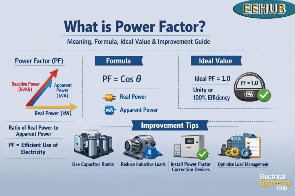
Table of Contents
Table of Contents
What is Power Factor?
Power Factor is the ratio of real power used by an AC load to the apparent power supplied to that load.
In simple language, it tells us how effectively an electrical system turns the power supplied by the source into useful real power.
Imagine a delivery truck that has space for 100 boxes but only 80 boxes contain useful products. The truck still has to travel with all 100 boxes of capacity. In a similar way, an AC electrical system with a low value may require more apparent-power capacity than the useful real-power requirement alone would suggest.
Resistive loads, such as traditional electric heaters, tend to have a value close to 1 because voltage and current are almost in phase.
Inductive loads, including induction motors, transformers, pumps, compressors, fans, and many HVAC systems, require reactive power to establish magnetic fields. This causes current to lag voltage and reduces the displacement value.
The quantity has no physical unit. It is expressed as a decimal from 0 to 1 or as a percentage.
Examples include:
| Value | Percentage |
|---|---|
| 1.00 | 100% |
| 0.98 | 98% |
| 0.95 | 95% |
| 0.90 | 90% |
| 0.80 | 80% |
| 0.70 | 70% |
Power Factor Formula & How It’s Calculated
The basic formula is:
PF = kW / kVA
Where:
- kW = real power or active power
- kVA = apparent power
- PF = power factor
For example, a factory motor system consumes 80 kW while the apparent load is 100 kVA.
PF = 80 / 100 = 0.80
The load therefore operates at 0.80.
Calculation Using kW and kVAR
When real power and reactive power are known, apparent power can be calculated using:
kVA = √(kW² + kVAR²)
The value can then be calculated as:
PF = kW / √(kW² + kVAR²)
For example:
- Real power = 100 kW
- Reactive power = 75 kVAR
Therefore:
kVA = √(100² + 75²)
kVA = 125 kVA
So:
PF = 100 / 125 = 0.80
This relationship is particularly useful when sizing capacitor banks and analyzing industrial electrical systems.
Leading vs Lagging Power Factor
A lagging value is common with inductive equipment. Motors and transformers require magnetizing current, causing current to lag the supply voltage.
A leading value occurs when capacitive reactive power exceeds the inductive requirement.
Capacitor banks are commonly installed to offset lagging reactive power. However, excessive capacitance can create an overly leading condition, so correction equipment should be selected according to measured operating conditions.
Why Power Factor Matters
The main reason the value matters is current.
For a three-phase system:
I = P / (√3 × V × PF)
Where:
- I = line current in amperes
- P = real power in watts
- V = line-to-line voltage
- PF = power factor
For a fixed kW load and supply voltage, a lower value requires higher current.
Consider a 100 kW three-phase load.
| PF | Approx. Current at 400 V | Approx. Current at 480 V |
|---|---|---|
| 0.70 | 206 A | 172 A |
| 0.80 | 180 A | 150 A |
| 0.90 | 160 A | 134 A |
| 0.95 | 152 A | 127 A |
| 1.00 | 144 A | 120 A |
The figures are theoretical values based on a balanced three-phase load and illustrate the relationship between real power, voltage, and current.
Effect on Electrical Losses
Cable losses are approximately proportional to current squared:
P loss = I²R
Therefore, when current increases, resistive losses can increase significantly.
For example, if current increases by 20%, the theoretical I²R loss increases by approximately:
1.2² = 1.44
That represents about 44% higher resistive loss for the same conductor resistance.
This is why improving a poor value can help reduce unnecessary current in distribution equipment.
Effect on Transformer Capacity
Transformers are normally rated in kVA rather than simply kW.
Consider a 500 kVA transformer.
At 0.80:
500 × 0.80 = 400 kW
At 0.95:
500 × 0.95 = 475 kW
The transformer can therefore support substantially more real power at a higher value, assuming thermal limits and other operating conditions are satisfied.
Effect on Generators
The same principle applies to generators.
A generator rated at 500 kVA does not necessarily deliver 500 kW. At 0.80, the corresponding real-power capacity is approximately 400 kW. At 0.95, it is approximately 475 kW, subject to the generator manufacturer’s limits.
A low value can therefore consume valuable generator capacity without increasing useful output.
Utility Charges and Demand
Some U.S. commercial and industrial utilities apply demand-related charges based on kW, kVA, kVAR, or a combination of these factors. Some utilities also apply a PF adjustment or minimum requirement.
European commercial and industrial electricity contracts may similarly account for reactive energy or excessive reactive demand.
There is no single global PF penalty rate. Charges vary by utility, country, tariff, voltage level, customer class, and contract.
Before installing correction equipment, check the current tariff and electricity bill for the specific facility.
Power Factor vs Efficiency
Power Factor and efficiency are related to electrical performance, but they measure different things.
| Feature | Power Factor | Efficiency |
|---|---|---|
| Main purpose | Shows relationship between real and apparent power | Shows useful output compared with input |
| Typical expression | 0–1 or % | 0–1 or % |
| Main concern | Reactive and distortion effects | Energy and equipment losses |
| Commonly affected by | Inductive loads, capacitive loads, harmonics | Copper, iron, mechanical and electronic losses |
| Capacitors directly improve it? | Yes, in suitable inductive systems | No, not directly |
A motor could have:
- Efficiency = 92%
- PF = 0.82
This does not mean that the motor wastes 18% of its electrical input as reactive power.
Efficiency describes energy conversion losses. The value describes how much apparent electrical power corresponds to real power.
A useful electrical system can therefore have both high efficiency and poor PF.
Ideal, Good & Acceptable Power Factor Values
The ideal value is 1.00, also called unity.
At unity:
kW = kVA
However, aiming for exactly 1.00 at every operating condition is not always necessary.
For many industrial applications, maintaining approximately 0.95 or higher is a practical target. Some facilities may aim for 0.98 or better where the tariff structure and operating conditions justify it.
| Value | Classification | General Interpretation |
|---|---|---|
| Below 0.80 | Poor | High reactive demand |
| 0.80–0.85 | Low | Significant opportunity for improvement |
| 0.85–0.90 | Acceptable | May be adequate depending on application |
| 0.90–0.95 | Good | Generally satisfactory |
| 0.95–0.99 | Excellent | Strong electrical utilization |
| 1.00 | Ideal | Unity condition |
These categories should not be treated as universal utility limits.
For example, one commercial tariff may begin applying a charge below a particular threshold while another may use a different method based on kVA demand or reactive energy.
The best target is therefore the value that provides technically sound operation and makes economic sense for the installation.
How to Check Power Factor
Checking power factor helps determine how efficiently electrical power is being used by a load. You can measure it directly with a power factor meter or calculate it from real and apparent power.
| Method | Formula / Reading | Best For |
|---|---|---|
| Power Factor Meter | Direct PF reading | Quick testing |
| Power Analyzer | PF, kW, kVA | Detailed analysis |
| Calculation | PF = kW ÷ kVA | Manual verification |
For practical testing, connect the measuring instrument according to the manufacturer’s instructions and record voltage, current, real power, and apparent power. A value closer to 1 indicates better utilization of supplied power.
For a detailed step-by-step procedure, formulas, and testing methods, see our guide on how to measure Power Factor.
How to Calculate Power Factor in Electricity Bill
Understanding power factor can help you interpret electricity bills, especially for commercial and industrial consumers. To calculate it, compare the real power (kW) used with the apparent power (kVA) supplied:
Power Factor = kW ÷ kVA
| Value | Example |
|---|---|
| Real Power | 80 kW |
| Apparent Power | 100 kVA |
| Power Factor | 0.80 |
For example, if your meter records 80 kW and 100 kVA, the power factor is 0.80 (80%). A lower value means the electrical system requires more current to deliver the same useful power and may result in penalties under certain utility tariffs.
For a step-by-step method, including bill readings and practical examples, see our detailed guide on How to Calculate Power Factor in Electricity Bill.
How to Improve Power Factor
Power Factor improvement is usually achieved by reducing the reactive power supplied through upstream distribution equipment.
Common methods include:
- Capacitor banks
- Automatic power-factor correction panels
- Synchronous condensers
- Proper motor selection
- Avoiding prolonged motor operation at very light loads
- Correct transformer sizing
- Reactive-power control through modern drives and inverters
- Harmonic filtering where distortion is significant
Capacitor Banks
Capacitor banks are one of the most common correction methods in commercial and industrial facilities.
A capacitor provides leading reactive power that offsets the lagging reactive power of inductive equipment.
There are two main approaches.
- Fixed capacitor banks are suitable when the reactive load remains relatively stable.
- Automatic capacitor banks, often called APFC panels, switch capacitor stages according to the measured load. They are more suitable for facilities where motor and process loads change throughout the day.
Capacitor Sizing Formula
The basic capacitor-sizing equation is:
Qc = P × (tan φ₁ − tan φ₂)
Where:
- Qc = required capacitor capacity in kVAR
- P = real power in kW
- φ₁ = initial phase angle
- φ₂ = target phase angle
For example, a 100 kW load operating at 0.75 and corrected to 0.95 requires approximately:
Qc ≈ 55 kVAR
The exact capacitor-bank selection should account for actual measured load, standard capacitor steps, harmonics, voltage, switching conditions, and the possibility of changing load levels.
A dedicated Power Factor Correction Calculator can be used to calculate the approximate kVAR requirement from the existing and target values.
Synchronous Condensers
A synchronous condenser is a synchronous machine operated primarily to provide or absorb reactive power.
It can be useful for large industrial facilities and power-system applications where dynamic reactive-power support is required.
For many ordinary commercial installations, capacitor banks or modern electronic compensation systems are simpler.
Avoiding No-Load Motor Operation
Induction motors can have a relatively poor value when operating at very light loads.
Leaving oversized motors running unnecessarily can increase reactive demand without providing useful mechanical output.
Better practices include:
- Switching off unused motors
- Selecting motors according to actual duty
- Avoiding excessive oversizing
- Using variable-speed drives where appropriate
- Maintaining motors correctly
Power Factor Improvement by Application
Different electrical systems require different approaches.
Industrial Power Factor Correction
Industrial plants often have significant inductive demand from:
- Pumps
- Compressors
- Fans
- Conveyors
- HVAC equipment
- Machine tools
- Elevators
- Large motors
- Welding equipment
- Transformers
A plant should ideally measure the value over an operating cycle rather than relying on one reading.
For example, a manufacturing facility might show 0.96 during the day but fall to 0.78 during periods when several large motors operate under unusual loading conditions.
An automatic correction system may be more suitable than a fixed capacitor bank in this situation.
Power Factor in Three-Phase Systems
Three-phase systems are common in commercial and industrial facilities worldwide.
The formula is:
PF = kW / kVA
And current can be calculated using:
I = kW × 1000 / (√3 × V × PF)
For a 50 kW load at 400 V:
- At 0.80:
- I ≈ 90 A
- At 0.95:
- I ≈ 76 A
For a U.S. 480 V system:
- At 0.80:
- I ≈ 75 A
- At 0.95:
- I ≈ 63 A
These calculations show why a higher value can reduce current requirements.
Single-Phase Systems
For single-phase systems:
I = P / (V × PF)
For example, a 5 kW load supplied at 240 V and 0.80 requires approximately:
I = 5,000 / (240 × 0.80)
I ≈ 26.0 A
At 0.95, the current falls to approximately:
21.9 A
The same principle applies to residential, commercial, and small industrial systems.
Residential Power Factor
Most residential customers in the United States and Europe do not need to install dedicated capacitor banks.
Residential electricity billing is commonly based on energy consumption in kWh, although tariff structures vary. Large commercial and industrial customers are more likely to encounter demand or reactive-power considerations.
Modern appliances such as variable-speed air conditioners, computers, televisions, LED drivers, and other electronic equipment may also incorporate power-factor correction or other techniques to improve their input characteristics.
Homeowners should therefore not purchase a capacitor device simply because a plug-in meter displays a low instantaneous reading.
The economic benefit should be established before installing correction equipment.
Power Factor in Specific Equipment
Transformer Power Factor
A transformer does not have one constant value.
Its input characteristics change with loading and with the type of equipment connected to its secondary side.
A lightly loaded transformer still requires magnetizing current. If the connected load is strongly inductive, the overall input value can be lower.
Transformer selection should therefore consider kVA loading, efficiency, harmonics, load characteristics, and the expected operating profile.
Motor Power Factor
Induction motors are among the most common sources of lagging reactive demand.
The motor needs magnetizing current to establish the magnetic field required for operation.
Motor PF is influenced by:
- Motor design
- Load level
- Voltage
- Speed
- Efficiency
- Operating conditions
- Drive technology
A motor operating close to its rated load generally performs better than a substantially oversized motor operating at very light load.
Inverter Power Factor
Modern power electronics can achieve high input values, but performance depends on the inverter topology and control system.
For grid-connected equipment, it is important to distinguish displacement PF from true PF.
Displacement PF considers the phase relationship between fundamental voltage and current.
True PF also considers waveform distortion caused by harmonics.
This distinction becomes increasingly important in facilities containing variable-frequency drives, UPS systems, rectifiers, LED drivers, and other nonlinear loads.
Power Factor in Solar Systems
Solar inverters can often control reactive power as well as active power.
Depending on the model and grid requirements, an inverter may operate at:
- Unity PF
- A fixed target value
- Leading PF
- Lagging PF
- Volt-var control
- Reactive-power control
The correct setting depends on the local grid code, utility requirements, inverter capabilities, and site design.
Solar generation can also change the net load seen by the utility. A facility with large motors may draw substantial reactive power even when its solar array is producing much of its daytime real-power demand.
For this reason, solar-system PF should be assessed at the point of common coupling and not only at individual equipment.
True Power Factor and Harmonic Distortion
Not every low value is caused by phase shift.
Modern electronic equipment can introduce harmonic currents into an electrical system. In such cases, the overall or true value can be affected by both displacement and distortion.
A simplified relationship is:
True PF = Displacement PF × Distortion Factor
This is particularly important in facilities containing:
- Variable-frequency drives
- UPS systems
- Data centers
- Battery chargers
- Solar inverters
- Rectifiers
- LED lighting
- Power electronics
Installing ordinary capacitors without considering harmonics can create unwanted resonance conditions.
In installations with substantial nonlinear loads, a power-quality study should be considered before selecting correction equipment.
Practical Example: Correcting an Industrial Load
Consider an industrial facility with:
- Real power = 200 kW
- Existing PF = 0.75
- Target PF = 0.95
Existing apparent power:
kVA = 200 / 0.75
kVA = 266.7 kVA
After correction:
kVA = 200 / 0.95
kVA = 210.5 kVA
The apparent-power requirement therefore falls by approximately:
266.7 − 210.5 = 56.2 kVA
This can release capacity in transformers, generators, cables, and switchgear.
The approximate capacitor requirement is:
Qc = P × (tan φ₁ − tan φ₂)
For these values, the required correction is approximately 110 kVAR.
The final equipment selection should not be based solely on this theoretical figure. A real installation should use measured load data and consider harmonic distortion, voltage, switching steps, load variation, and the manufacturer’s recommendations.
Common Mistakes When Improving Power Factor
Installing Excessive Capacitance
More capacitance is not always better.
Overcorrection can create a leading condition and may result in undesirable voltage or resonance effects.
Ignoring Harmonics
Capacitors can interact with harmonic currents.
Facilities with large numbers of drives, UPS systems, rectifiers, or other nonlinear loads should assess harmonic levels before installing a conventional capacitor bank.
Using a Fixed Bank for a Highly Variable Load
A fixed capacitor bank may work well with a stable load but can cause overcorrection when the facility operates at low load.
Automatic capacitor switching or a dynamic compensation system may be more appropriate.
Correcting Without Measuring
A nameplate value is not enough to determine the required correction capacity.
Ideally, measure:
- kW
- kVA
- kVAR
- PF
- Voltage
- Current
- Harmonic distortion
- Load variation over time
A power-quality analyzer or suitable power meter can provide much better information.
Power Factor Correction Capacitor Calculator
A power factor correction capacitor calculator helps determine the capacitor size needed to improve a motor or industrial load’s power factor. By entering the existing kW, present power factor, and desired power factor, you can estimate the required reactive power compensation in kVAR.
| Input | Example |
|---|---|
| Load | 50 kW |
| Existing PF | 0.75 |
| Target PF | 0.95 |
| Required correction | ≈ 27.7 kVAR |
The calculation is based on:
Qc = P × (tan φ₁ − tan φ₂)
where Qc is capacitor rating in kVAR and P is active power in kW. For a step-by-step calculation, capacitor sizing method, and practical examples, use our Power Factor Correction Capacitor Calculator. It can help select an appropriate capacitor bank while avoiding excessive correction and poor system performance.
Power Factor vs Service Factor
Power factor and service factor are different electrical concepts, although both are important when evaluating motors and electrical equipment. Power factor measures how effectively electrical power is converted into useful work, while service factor indicates how much additional load a motor can handle under specified conditions.
| Feature | Power Factor | Service Factor |
|---|---|---|
| Meaning | Efficiency of electrical power usage | Permitted overload capacity |
| Typical value | 0 to 1 | Usually 1.0–1.25 |
| Applies to | AC electrical loads | Mainly motors |
| Main concern | Reactive power and efficiency | Motor load capability |
Understanding Power Factor vs Service Factor helps prevent confusion when sizing motors, correcting reactive power, or evaluating equipment ratings. Read our detailed guide on differences here.
Automatic Power Factor Correction Using Arduino
An Arduino-based system can automate power factor correction by monitoring voltage and current, calculating the power factor, and switching capacitor banks through relays when reactive power increases. This approach is useful for small workshops, laboratories, and educational projects where a low-cost automatic controller is required.
| Parameter | Typical Function |
|---|---|
| Arduino Uno | Main control unit |
| Current sensor | Measures load current |
| Voltage sensor | Measures AC voltage |
| Capacitor bank | Supplies reactive power |
| Relay module | Switches capacitors |
The controller can progressively connect capacitors to maintain a target power factor, such as 0.95 or higher.
Safety: AC capacitor banks require proper protection, discharge resistors, contactors, and electrical isolation. DIY mains-voltage projects should be designed and tested by a qualified professional.
Power Factor vs Crest Factor
Power factor and crest factor describe different characteristics of an electrical waveform. Power Factor vs Crest Factor becomes important when evaluating motors, power supplies, inverters, and nonlinear loads. Power factor measures how effectively electrical power is converted into useful work, while crest factor compares the peak current or voltage with its RMS value.
| Parameter | Power Factor | Crest Factor |
|---|---|---|
| Measures | Power-use efficiency | Waveform peak level |
| Formula | kW ÷ kVA | Peak ÷ RMS |
| Typical concern | Energy efficiency | Peak current stress |
Understanding these differences helps with equipment sizing, harmonic analysis, and power-quality assessments. For a detailed explanation, formulas, and practical examples, see our complete guide to Power Factor vs Crest Factor.
Power Factor Correction Devices to Buy
Choosing the right equipment can improve electrical efficiency, reduce reactive power demand, and help lower avoidable electricity costs. Common options include capacitor banks, automatic power factor correction (APFC) panels, and active power factor correction systems.
| Device | Best For | Main Benefit |
|---|---|---|
| Capacitor Bank | Workshops & motors | Simple reactive power compensation |
| APFC Panel | Commercial facilities | Automatic PF correction |
| Active PFC | Sensitive equipment | Precise correction |
Before purchasing, check your existing power factor, system voltage, load profile, and required kVAR capacity.
For a detailed comparison of suitable models, specifications, and buying considerations, see our guide to Power Factor Correction Devices to Buy, which can help you select the right solution for your application.
Frequently Asked Questions
What is power factor and why is it important?
Power Factor is the ratio of real power to apparent power in an AC electrical system. It is important because a low value requires more current to deliver the same useful kW load. This can increase cable losses, voltage drop, transformer loading, generator requirements, and potentially utility charges.
What is a good or ideal power factor?
The ideal value is 1.00, or unity. For many commercial and industrial systems, 0.95 or higher is considered a strong practical target. However, the actual required minimum depends on the utility tariff, electrical system, and application.
How do I calculate power factor?
Use:
PF = kW / kVA
If kW and kVAR are available:
PF = kW / √(kW² + kVAR²)
For example, 80 kW and 100 kVA produce a value of 0.80.
What is power factor in solar systems?
Solar inverters can often operate at unity or provide controlled reactive power. Their capability may include fixed PF, reactive-power control, or Volt-VAR functions. The correct setting depends on the inverter, utility requirements, grid code, and electrical design.
What is power factor in Hindi?
पावर फैक्टर (Power Factor) वास्तविक शक्ति और Apparent Power के बीच का अनुपात है। यह बताता है कि AC विद्युत प्रणाली उपलब्ध विद्युत क्षमता का कितनी प्रभावी तरीके से उपयोग कर रही है। इसका मान सामान्यतः 0 से 1 के बीच होता है और 1 को Unity Power Factor कहा जाता है।
Final Takeaway
Power Factor provides a useful picture of how an AC electrical system uses its apparent-power capacity. A low value does not mean that all of the supplied electricity is being wasted, but it can cause higher current and place additional demand on cables, transformers, generators, and distribution equipment.
For residential users, dedicated correction is usually unnecessary unless a specific technical or billing reason exists. For commercial and industrial facilities, especially those operating large motors, compressors, pumps, HVAC systems, transformers, drives, and other inductive equipment, improving a poor value can provide meaningful electrical and economic benefits.
A value around 0.95 or higher is often a practical industrial target, while 1.00 is the theoretical ideal. However, the best target should always be based on the actual load profile, utility tariff, equipment characteristics, harmonics, and applicable electrical requirements.
For U.S. installations, engineers should consider the applicable NEC requirements and utility service conditions. European projects should consider relevant IEC/EN standards, local grid codes, and the requirements of the electricity supplier or distribution network operator.
The most reliable approach is simple: measure first, calculate the reactive-power requirement, check the tariff and grid requirements, assess harmonics, and then select the appropriate correction method.
Get new guides in your feed. Follow Electrical Insights on LinkedIn for new electrical standards guides, calculators and design tips from Azad Circuit Hub.
PowerFactor, #PowerFactorCorrection, #ElectricalEngineering, #PowerFactorFormula, #PowerQuality, #ElectricalPower, #EnergyEfficiency, #PowerFactorImprovement, #ACPower, #ElectricalSystems
