
Power Factor Correction Capacitor Calculator: Best Tool
A Power Factor Correction Capacitor Calculator helps determine the capacitor size required to improve the power factor of an AC electrical system. It is useful for motors, pumps, compressors, transformers, HVAC equipment, and industrial distribution systems where inductive loads draw reactive power.
A low power factor increases current, causes additional losses, reduces available system capacity, and may increase electricity charges where utilities apply power factor penalties or demand adjustments.
Power Factor Correction Capacitor Calculator
Power Factor Correction Capacitor Calculator
Work out the reactive power (kVAR) and capacitor size needed to raise your load’s power factor to a target value, for single-phase or three-phase systems, with a side-by-side before/after comparison.
Load and System Details
Capacitor Bank Specification
Power Triangle: Before vs After
Before / After Summary
| Parameter | Before | After |
|---|
How to Use This Tool
- Enter your load’s active power in kW, taken from a bill, meter, or nameplate rating.
- Choose whether you know your existing power factor directly, or only the existing reactive power (kVAR) from a power quality meter.
- Set the target power factor you want to reach – this is usually the level your utility requires to avoid a low power factor penalty.
- Select single-phase or three-phase, and enter the system voltage. For three-phase systems, also choose whether the capacitor bank will be wired in delta or star.
- Confirm the system frequency and click Calculate to see the required capacitor bank size, capacitance per phase, and the expected reduction in line current.
- Use the before/after comparison and power triangle to understand how much apparent power (kVA) and current the correction removes from the supply.
Technical Notes
Why Power Factor Correction Matters
A low power factor means the supply has to carry more current than the load’s real work actually requires, because part of that current is used just to build up magnetic fields in motors, transformers, and other inductive equipment. Correcting the power factor supplies that magnetizing current locally, from capacitors, so the incoming supply only has to carry current for the useful work being done.
Delta vs Star Capacitor Banks
A delta-connected bank sees the full line-to-line voltage across each capacitor, so it needs less capacitance to deliver the same reactive power. A star-connected bank sees only the lower line-to-neutral voltage across each unit, so more capacitance is required per phase to reach the same rating. Delta is the more common industrial arrangement for this reason.
Sizing the Bank Correctly
Oversizing a capacitor bank can push the power factor past unity into a leading condition, which can cause voltage rise and is discouraged by most utilities. It is common practice to target a slightly lagging power factor, such as 0.95 to 0.98, rather than exactly 1.00, and to size the bank in stages if the load varies significantly through the day.
Where This Fits in a Larger System
This calculator sizes the capacitor bank itself. It does not replace a full harmonic assessment, and on sites with variable frequency drives or other non-linear loads, a qualified engineer should check for harmonic resonance risk before installing fixed capacitors, since capacitors can amplify certain harmonic currents if sized without that check.
This tool provides an engineering estimate for capacitor sizing based on standard power triangle relationships. Actual capacitor bank selection should account for harmonic content, switching transients, ambient temperature, and manufacturer derating factors, and should be verified by a qualified electrical engineer against the applicable local code or utility requirement before installation.
Quick Comparison: Capacitor Size by Power Factor
| Real Power | Existing PF | Target PF | Required Capacitor |
|---|---|---|---|
| 10 kW | 0.70 | 0.95 | 6.92 kVAr |
| 25 kW | 0.75 | 0.95 | 13.07 kVAr |
| 50 kW | 0.75 | 0.95 | 26.14 kVAr |
| 100 kW | 0.80 | 0.95 | 32.86 kVAr |
| 250 kW | 0.80 | 0.95 | 82.14 kVAr |
Values are approximate and assume a steady three-phase load. Final capacitor selection should consider voltage, harmonics, switching conditions, and the actual load profile.
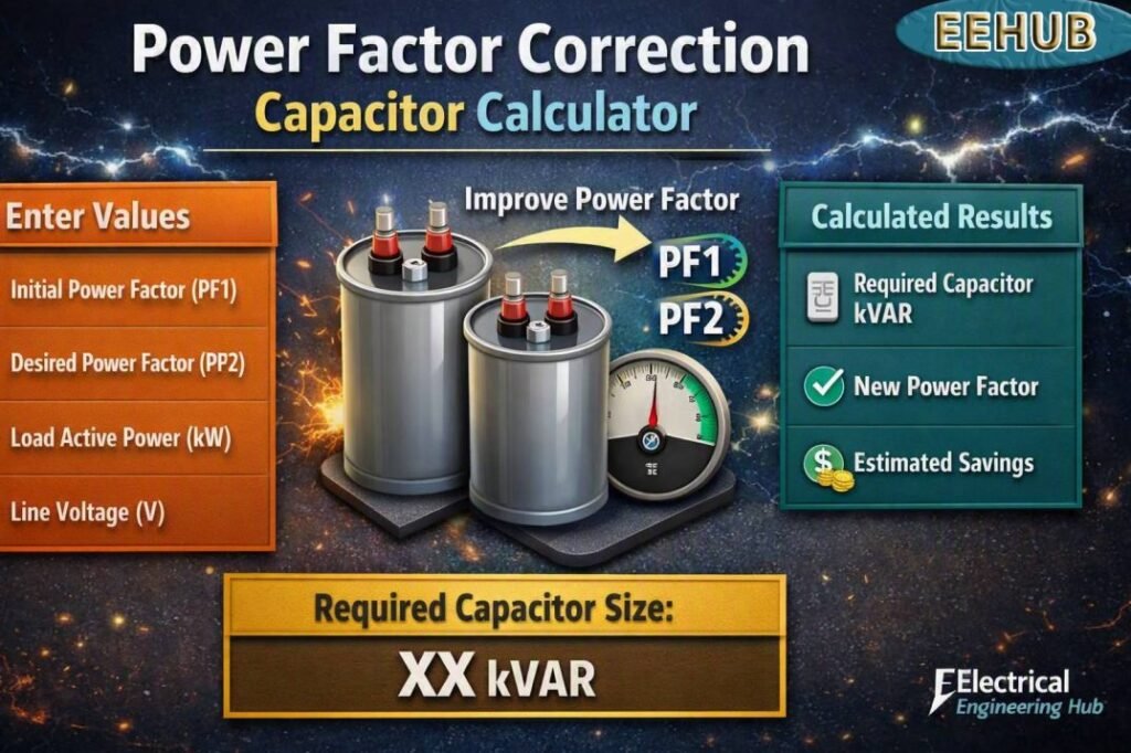
Table of Contents
Table of Contents
What Is Power Factor Correction?
Power factor correction improves the relationship between real power and apparent power in an AC system. Motors and other inductive equipment need reactive power to establish magnetic fields. This reactive component increases current without producing useful mechanical output.
A capacitor supplies leading reactive power, which offsets part of the lagging reactive power produced by inductive loads. As a result, the required line current can fall while the useful kW load remains unchanged.
For example, a 100 kW motor operating at 0.80 power factor requires considerably more apparent power than the same motor operating at 0.95 power factor.
The basic relationship is:
Power Factor = kW / kVA
A higher power factor means that more of the supplied apparent power is being converted into useful real power.
If you are also planning a broader power factor improvement strategy, review the load profile before selecting individual capacitor steps.
Power Factor Correction Capacitor Calculator Formula
The standard capacitor sizing formula is:
Qc = P × (tan φ₁ − tan φ₂)
Where:
- Qc = required capacitor rating in kVAr
- P = active power in kW
- φ₁ = angle corresponding to the existing power factor
- φ₂ = angle corresponding to the desired power factor
- PF₁ = existing power factor
- PF₂ = target power factor
The angles can be calculated using:
φ = cos⁻¹(PF)
This formula is widely used for sizing shunt capacitors in industrial and commercial electrical systems.
How to Calculate Capacitor Size
Consider a 50 kW motor with an existing power factor of 0.75. Suppose the desired power factor is 0.95.
First calculate the two power factor angles:
φ₁ = cos⁻¹(0.75)
φ₂ = cos⁻¹(0.95)
The corresponding tangent values are approximately:
- tan φ₁ = 0.882
- tan φ₂ = 0.329
Therefore:
Qc = 50 × (0.882 − 0.329)
Qc ≈ 27.65 kVAr
A practical installation could therefore use a capacitor bank close to 30 kVAr, subject to engineering verification.
The Power Factor Correction Capacitor Calculator gives the theoretical reactive compensation requirement. The final standard capacitor rating may need to be adjusted to match available equipment sizes and operating conditions.
Three-Phase Capacitor Sizing
Three-phase systems are common in factories, commercial buildings, data centers, and large HVAC installations.
For a balanced three-phase system, capacitor reactive power can be expressed as:
Qc = √3 × V × I × sin φ
For capacitor current, the relationship depends on whether the capacitors are connected in delta or star.
A capacitor bank rated in kVAr is generally easier to specify because manufacturers commonly provide standard ratings such as:
| Typical Bank Size | Common Application |
|---|---|
| 5 kVAr | Small motors and commercial loads |
| 10 kVAr | Small industrial feeders |
| 20 kVAr | Medium motor groups |
| 25 kVAr | Industrial distribution |
| 30 kVAr | Medium-sized facilities |
| 50 kVAr | Large motor groups |
| 100 kVAr | Industrial main panels |
| 200+ kVAr | Large plants and substations |
Automatic power factor correction panels normally combine several capacitor steps so that compensation follows the changing load.
Fixed vs Automatic Capacitor Banks
A fixed capacitor can work well when the load remains relatively constant. For example, a dedicated motor that runs for long periods at a predictable load may use a fixed capacitor.
Automatic capacitor banks are better when the electrical load changes throughout the day. A power factor controller switches capacitor stages in and out according to measured reactive demand.
| Feature | Fixed Capacitor | Automatic Capacitor Bank |
|---|---|---|
| Load variation | Poor fit | Excellent fit |
| Cost | Lower | Higher |
| Control | Manual/fixed | Automatic |
| Overcorrection risk | Higher | Lower |
| Industrial suitability | Constant loads | Variable loads |
| Maintenance | Low | Moderate |
For a factory with multiple motors operating at different times, automatic compensation is usually more practical.
Electricity Cost and Potential Savings
Capacitor correction does not normally reduce the kWh consumed by the actual mechanical load. Its main benefits come from reducing reactive current, losses, demand-related charges, and possible utility power factor penalties.
Actual electricity rates vary significantly by country, utility, tariff class, season, and time of use. For a simple example, assume an electricity rate of $0.15/kWh.
If an installation uses 100,000 kWh per month, its energy charge at this assumed rate would be:
100,000 × $0.15 = $15,000 per month
The actual financial benefit from correction depends on the utility’s billing structure. Some commercial and industrial tariffs use demand charges, while others impose penalties when the power factor falls below a specified threshold.
Therefore, capacitor sizing should be based on the utility tariff as well as the electrical measurements.
Capacitor Bank Cost
Capacitor prices vary according to voltage rating, manufacturer, switching method, harmonic protection, enclosure, controller, and installation requirements.
As a broad 2026 budgeting example, a basic low-voltage capacitor bank may cost roughly $60–$150 per kVAr for equipment, while a complete automatic panel with contactors, controller, protection, enclosure, and harmonic considerations can be considerably higher.
These are planning figures rather than fixed market rates. Obtain current quotations before preparing a project budget.
For facilities considering a complete power factor improvement project, compare the capacitor investment with potential demand savings and utility penalties over the expected service life.
Important Factors Before Installing Capacitors
A calculated kVAr value is only the starting point. Several engineering factors should be checked before installation.
Harmonic Distortion
Variable frequency drives, UPS systems, rectifiers, LED drivers, and other nonlinear loads can produce harmonics. Capacitors may interact with system inductance and create resonance.
Where harmonic levels are significant, a detuned capacitor bank or harmonic filter may be required.
System Voltage
Capacitors must have an appropriate voltage rating. A 400 V system, for example, requires capacitors designed for the applicable operating voltage and connection arrangement.
Load Variation
Avoid installing a large fixed capacitor on a highly variable load. Excessive correction can produce a leading power factor and undesirable voltage conditions.
Motor Switching
Motor-connected capacitors require careful consideration of switching arrangements. Incorrect connections can result in transient overvoltages or other equipment problems.
Measurement
Ideally, measure real power, reactive power, current, voltage, and power factor over a representative operating period. A single instantaneous reading may not represent the facility’s actual demand.
Practical Capacitor Selection Example
Suppose a facility has:
- Load: 150 kW
- Existing PF: 0.78
- Target PF: 0.95
Using the standard equation:
Qc = 150 × [tan(cos⁻¹ 0.78) − tan(cos⁻¹ 0.95)]
The required compensation is approximately 69.8 kVAr.
A designer may consider a 70 kVAr bank, or a staged arrangement such as 10 + 10 + 10 + 20 + 20 kVAr, depending on the load profile and available equipment.
The Power Factor Correction Capacitor Calculator result should therefore be treated as the calculated reactive requirement rather than an automatic instruction to purchase the nearest capacitor.
Benefits of Power Factor Correction
Proper correction can provide several practical benefits:
- Lower line current
- Reduced I²R losses
- Better transformer capacity utilization
- Reduced voltage drop
- Improved electrical system efficiency
- Lower demand-related costs in applicable tariffs
- Reduced utility power factor penalties
- Additional capacity on existing feeders and transformers
However, capacitors should not be oversized simply to achieve the highest possible power factor. A target around 0.95 to 0.99 is often more practical than attempting to maintain exactly 1.00 under all operating conditions.
Frequently Asked Questions
1. What size capacitor do I need to improve power factor?
The required size depends on load kW, existing power factor, and target power factor. Use Qc = P(tanφ₁ − tanφ₂) to calculate the required kVAr.
2. Can a capacitor improve motor efficiency?
A capacitor does not directly increase the motor’s mechanical efficiency. It reduces the reactive current supplied through upstream conductors and equipment, which can reduce electrical losses and improve system utilization.
3. What is a good target power factor?
A target between approximately 0.95 and 0.99 is commonly practical. The ideal target depends on the utility tariff, equipment, load variation, and system design.
4. Can I use one capacitor for several motors?
It is possible to use a central capacitor bank for several motors. Automatic capacitor banks are often preferred where motors switch on and off frequently because compensation can follow the changing reactive load.
5. Are capacitor banks suitable for systems with VFDs?
They can be used, but harmonic analysis is important. VFD-heavy systems may require detuned reactors or harmonic filters to avoid resonance and excessive capacitor stress.
Final Takeaway
A Power Factor Correction Capacitor Calculator provides a quick way to estimate the kVAr compensation needed to move an electrical system from its present power factor to a desired target. The key inputs are real power, existing power factor, and target power factor.
For reliable results, combine the calculated value with actual load measurements, utility billing rules, voltage conditions, harmonic data, and the operating pattern of the facility.
If your goal is to reduce electrical losses and utility-related costs, a properly designed power factor improvement system can be a worthwhile upgrade, especially in large commercial and industrial installations.
The Power Factor Correction Capacitor Calculator is most useful when treated as the first stage of the design process rather than the final equipment selection. Always verify the capacitor rating, switching method, protection, harmonics, and installation requirements before commissioning a correction system.
Get new guides in your feed. Follow Electrical Insights on LinkedIn for new electrical standards guides, calculators and design tips from Azad Circuit Hub.
PowerFactorCorrection, #CapacitorCalculator, #PowerFactor, #PowerFactorImprovement, #KVARCalculator, #ElectricalEngineering, #PowerFactorCorrectionCapacitor, #CapacitorSizing, #ReactivePower, #ElectricalCalculators
Power Factor Correction Capacitor Calculator: Best Tool
Power Factor Correction Capacitor Calculator to determine the required capacitor kVAR, improve power factor, reduce reactive power, and optimize electrical system efficiency with practical formulas and examples.
Price Currency: USD
Operating System: All
Application Category: UtilitiesApplication
