ESP32 DevKit V1 Schematic: Circuit Diagram, Pinout & Design Guide (2026)
The ESP32 DevKit V1 schematic is built from five simple blocks: a USB connector, an AMS1117 3.3 V regulator, a CP2102 (or CH340) USB-to-UART chip, a two-transistor auto-reset circuit, and the ESP32-WROOM-32 module. Once you can read those five blocks, every upload error, brownout and boot-loop on this board becomes much easier to diagnose.
This guide walks through the circuit diagram block by block, gives you a colour-coded 30-pin pinout, explains the strapping pins that break most beginner projects, and shows how to reuse the design on your own PCB.
Quick answer: The ESP32 DevKit V1 schematic shows USB 5 V entering an AMS1117-3.3 regulator that feeds the ESP32-WROOM-32 module. A CP2102 bridge connects USB to UART0 (GPIO1/GPIO3), and its DTR and RTS lines drive two transistors that pull EN and GPIO0 low automatically so code uploads without pressing buttons.
Table of Contents
Table of Contents

ESP32 DevKit V1 Schematic Overview
The DevKit V1 was originally published by DOIT. Today almost every board sold as “ESP32 DevKit V1” is an unbranded clone with the same ESP32-WROOM-32 module and the same 30-pin layout. The architecture is identical across clones, but small details differ: the USB chip may be a CP2102 or a CH340, the regulator may be a genuine AMS1117 or a clone, and some boards omit a capacitor on EN.
That is why this guide shows the circuit blocks and what they do, rather than pretending one drawing is correct for every board on Amazon or AliExpress.
ESP32 DevKit V1 vs DevKitC V4 vs ESP32-S3 DevKitC-1
Many people searching for an “ESP32 dev board schematic” actually have one of these three boards. They are not interchangeable.
| Feature | DevKit V1 (DOIT-style) | Espressif DevKitC V4 | ESP32-S3-DevKitC-1 |
|---|---|---|---|
| Maker | DOIT and many clones | Espressif (official) | Espressif (official) |
| Chip | ESP32 (Xtensa LX6, dual core) | ESP32 (Xtensa LX6, dual core) | ESP32-S3 (Xtensa LX7, dual core) |
| Header pins | 30 (15 per side) | 38 (19 per side) | 44 (22 per side) |
| USB-UART | CP2102 or CH340 | CP2102N | CP2102N plus native USB |
| Schematic source | Community and clone vendors | Published by Espressif | Published by Espressif |
| Use this guide’s pinout? | Yes | Mostly (extra pins), check silkscreen | No, different chip and pin rules |
If your board has 38 pins and an Espressif logo, use this guide for the concepts and Espressif’s own schematic for exact values. If it has an ESP32-S3 module, do not reuse the ESP32 pin tables below.
ESP32 DevKit V1 Circuit Diagram: Block by Block
| Block | Typical parts | Job |
|---|---|---|
| USB input | Micro-USB connector | 5 V power and data |
| Regulator | AMS1117-3.3, input and output capacitors | 5 V to 3.3 V |
| USB-UART bridge | CP2102 or CH340 | USB to serial on UART0 |
| Auto-reset | 2 NPN transistors, 2 resistors | Drives EN and GPIO0 from DTR/RTS |
| Buttons | EN, BOOT | Manual reset and download mode |
| Module | ESP32-WROOM-32 | CPU, Wi-Fi, Bluetooth, 4 MB flash |
| Indicators | Power LED, blue LED on GPIO2 | Status |
ESP32 DevKit V1 Power Supply Circuit

The ESP32 itself runs from 3.3 V. The board gets there in three ways:
- Micro-USB (5 V): the normal route, through the AMS1117.
- VIN pin (about 5 V): also goes through the AMS1117.
- 3V3 pin: connects straight to the 3.3 V rail and bypasses the regulator. Treat it as an output for sensors. Feeding it 5 V can destroy the chip.
Things the schematic tells you that datasheets for the module do not:
- The AMS1117 is rated for roughly 800 mA with about 1.1 V dropout. Espressif’s hardware design guidelines call for a 3.3 V supply that can deliver at least 500 mA, because Wi-Fi transmit bursts are short but heavy. A poor USB cable or a weak hub port therefore shows up as random resets and the message Brownout detector was triggered.
- Many clones have no diode between VIN and the USB 5 V line. Do not connect USB and an external 5 V supply at the same time unless you have confirmed your board is protected.
- ESP32 GPIO pins are 3.3 V only. Use a level shifter for any 5 V logic.
USB-to-UART Bridge (CP2102 and CH340)
The bridge converts USB to serial and connects to UART0: TX0 = GPIO1, RX0 = GPIO3. That is why GPIO1 and GPIO3 should stay free if you want Serial Monitor and uploads to keep working.
| Bridge | Driver | Notes |
|---|---|---|
| CP2102 | Silicon Labs CP210x driver | Common on DOIT-style boards, reliable at high baud rates |
| CH340 | WCH CH340 driver | Cheaper clones, works fine but needs its own driver on some systems |
If your COM port does not appear, the fix is nearly always the driver or a charge-only USB cable, not the schematic.
ESP32 DevKit V1 Auto-Reset and Boot Circuit

This is the part of the schematic most guides skip, and it explains the most common upload error.
- EN is the reset line. It has a pull-up resistor (typically 10 kΩ) and a capacitor, and the EN button pulls it to ground.
- GPIO0 selects the boot mode. Held low at reset, the ESP32 enters download mode. Otherwise it runs your program.
- The USB-UART chip’s DTR and RTS outputs drive two transistors. The upload tool toggles them in sequence: GPIO0 goes low, EN pulses low, then both release. The ESP32 restarts in download mode with no button presses.
| GPIO0 at reset | Result |
|---|---|
| HIGH (default, internal pull-up) | Normal boot, runs your code |
| LOW | Download mode, ready for flashing |
If you see “Failed to connect to ESP32: Timed out waiting for packet header”: hold BOOT, tap EN, release BOOT when “Connecting……” turns into upload progress. If you must do this every time, your clone probably lacks the EN capacitor. Adding roughly 10 µF between EN and GND is a widely used fix.
ESP32 DevKit V1 Pinout Diagram (30-Pin)

The board exposes 25 usable GPIO, GND, VIN and 3V3. Always compare with the silkscreen on your own board, because some clones label pins differently.
| Function | Pins | Notes |
|---|---|---|
| Input-only GPIO | 34, 35, 36 (VP), 39 (VN) | No internal pull-up or pull-down |
| ADC1 | 32, 33, 34, 35, 36, 39 | Safe to use with Wi-Fi on |
| ADC2 | 0, 2, 4, 12, 13, 14, 15, 25, 26, 27 | Do not work while Wi-Fi is active |
| DAC | 25, 26 | 8-bit outputs |
| Touch | 4, 0, 2, 15, 13, 12, 14, 27, 33, 32 | Capacitive touch sensing |
| I2C (default) | SDA 21, SCL 22 | Remappable in software |
| SPI (VSPI default) | MOSI 23, MISO 19, SCK 18, CS 5 | HSPI: 13, 12, 14, 15 |
| UART0 (USB) | TX 1, RX 3 | Used by the USB-UART chip |
| UART2 | TX 17, RX 16 | Free for GPS, sensors |
| PWM | Any output-capable GPIO | LEDC peripheral |
| On-board LED | GPIO2 | Blue LED on DOIT-style boards |
Our earlier version listed GPIO0 to GPIO39 as general digital I/O. That was too loose: GPIO6 to 11 are wired to the internal flash and must never be used, and some numbers in that range do not exist on this module.
For a deeper explanation of every GPIO function across the family, see the full ESP32 pinout and GPIO pins guide.
Strapping Pins and Pins to Avoid
Strapping pins are read by the chip at reset to decide how to boot. Anything you attach to them can stop the board from starting.
| Pin | What it controls | Rule of thumb |
|---|---|---|
| GPIO0 | Boot mode (low = download) | Do not hold low at power-up unless you mean to flash |
| GPIO2 | Must be low or floating for download mode; drives the on-board LED | Avoid strong pull-ups |
| GPIO5 | Boot timing | Usually fine, avoid heavy loads at reset |
| GPIO12 (MTDI) | Flash voltage selection | Must be low at boot on this module. High causes boot failure |
| GPIO15 (MTDO) | Boot log output | Pulling low silences boot messages |
Other pins to treat carefully:
- GPIO6 to GPIO11: connected to the flash. Never use.
- GPIO1 and GPIO3: used by USB serial.
- GPIO34 to GPIO39: input only.
If you are connecting stepper drivers, see our A4988 with ESP32 wiring guide for pin choices that avoid these traps.
ESP32 DevKit V1 Schematic PDF: Where to Get It and Which One to Trust
People search for the “ESP32 DevKit V1 schematic PDF” and “DOIT ESP32 DevKit V1 schematic” because the clone market makes it hard to know which drawing matches the board in front of them. A practical approach:
- Identify your board first. Count pins, read the USB chip marking (CP2102 or CH340), and check for a DOIT or Espressif logo.
- If it is a 38-pin Espressif board, download the official schematic from Espressif’s ESP32-DevKitC documentation.
- If it is a no-name 30-pin clone, use the block diagram above and probe your board (see the multimeter section). Espressif staff have noted on the ESP32 forum that such boards are generic designs and the PCB silkscreen is the best reference.
- If you only need a symbol and footprint for your CAD project, library entries on sites such as EasyEDA or Flux are convenient. They are part libraries, so verify them against the datasheet before ordering a PCB.
For the module itself, rely on Espressif’s ESP32 datasheet and hardware design guidelines.
Designing Your Own ESP32 Board from the DevKit V1 Schematic
When you move from a dev board to custom hardware, keep these rules from the schematic and the Espressif guidelines:
- Use a regulator rated for at least 500 mA, with bulk and 100 nF decoupling close to the module’s 3V3 pin.
- Add an RC network on EN (10 kΩ pull-up with roughly 1 µF) for a clean power-up.
- Break out GPIO0 and the UART0 pins so you can always flash the board.
- Keep copper, traces and components away from the antenna area, and place the antenna at the board edge.
- Add ESD protection on the USB lines and a reverse-polarity or ideal-diode stage if you accept external power.
- Use a solid ground plane and short return paths.
To estimate the supply cable and conductor sizes when your ESP32 board sits inside a larger installation, use our DC cable size calculator.
Test Your ESP32 DevKit V1 with a Multimeter
Because components vary between clones, the fastest way to trust a schematic is to measure your own board. You need a basic multimeter. A typical auto-ranging digital multimeter is plenty for this job.
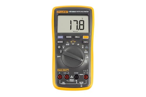
| Test | Expected | If wrong |
|---|---|---|
| USB 5 V pin to GND | about 4.8 to 5.2 V | Bad cable or port |
| 3V3 pin to GND | about 3.2 to 3.4 V | Regulator fault or overload |
| EN to GND (idle) | about 3.3 V | Missing pull-up or EN stuck low |
| GPIO0 to GND (idle) | about 3.3 V | BOOT button stuck or pin shorted |
| Continuity: BOOT button | Closes to GND when pressed | Dead button |
| Regulator output while running Wi-Fi | stays above about 3.0 V | Supply too weak, brownouts |
Troubleshooting Using the Schematic
| Symptom | Likely cause in the circuit | Fix |
|---|---|---|
| Port not detected | USB-UART driver missing or charge-only cable | Install CP210x or CH340 driver, change cable |
| Timed out waiting for packet header | Auto-reset not triggering | Hold BOOT during connect, add about 10 µF on EN |
| Brownout detector triggered | Weak 5 V, long cable, AMS1117 overloaded | Short good cable, powered hub, external 5 V to VIN |
| Boot loop after adding a sensor | Sensor holds a strapping pin at reset | Move it off GPIO0, 2, 12, 15 |
| Analog reads fail when Wi-Fi starts | Sensor on an ADC2 pin | Move to ADC1 (GPIO32 to 39) |
| Board hot near regulator | Too much 3.3 V load | Power big loads separately |
| Serial Monitor shows garbage | Wrong baud rate | Match the sketch, commonly 115200 |
Build Something with It
Once the schematic makes sense, put it to work:
- Read temperature on an I2C bus using GPIO21 and GPIO22. Our humidity sensor guide and OLED display comparison help you pick parts.
- Drive a stepper with the 28BYJ-48 and A4988 guide.
- Add classic Bluetooth serial with the HC-05 Bluetooth module guide, though the ESP32 already has Bluetooth built in.
- Moving from an older board? See ESP12F vs ESP32, the ESP8266 pinout and the ESP8266MOD WLED setup.
- Choosing between boards? Compare options in Raspberry Pi vs Arduino, ESP32, BeagleBoard and Pi Pico and check the Arduino Uno R3 pinout.
Recommended Gear for ESP32 DevKit V1 Projects


Frequently Asked Questions
What does the ESP32 DevKit V1 schematic show?
It shows how USB power, the AMS1117 3.3 V regulator, the CP2102 or CH340 USB-UART chip, the auto-reset transistors, the EN and BOOT buttons and the ESP32-WROOM-32 module are connected.
Is the ESP32 DevKit V1 30-pin or 38-pin?
The DOIT-style DevKit V1 is the 30-pin board. The 38-pin layout belongs to boards like Espressif’s DevKitC.
Which USB chip does the ESP32 DevKit V1 use?
Most DOIT-style boards use a CP2102. Many clones use a CH340. Both work; they need different drivers.
Can I power the ESP32 DevKit V1 from 5 V on the VIN pin?
Yes. VIN feeds the onboard regulator. Do not connect external 5 V and USB together unless your board has protection.
Can I put 5 V into the 3V3 pin?
No. That pin bypasses the regulator and 5 V can destroy the ESP32.
Why does my ESP32 DevKit V1 not enter download mode?
The auto-reset circuit may not be triggering. Hold BOOT while connecting, check your cable and driver, and consider adding a capacitor on EN.
Which pins should I avoid on the ESP32 DevKit V1?
Avoid GPIO6 to 11 (flash), be careful with strapping pins 0, 2, 5, 12 and 15, and remember GPIO34 to 39 are input only.
Does the ESP32 DevKit V1 work with the Arduino IDE?
Yes. Select the board named DOIT ESP32 DEVKIT V1 in the ESP32 board package, or use ESP32 Dev Module.
Where can I download the ESP32 DevKit V1 schematic PDF?
See the schematic PDF section above. The right file depends on whether you have a DOIT-style 30-pin clone or an Espressif 38-pin DevKitC.
How This Guide Was Prepared
Pin functions, strapping behaviour, ADC2 and Wi-Fi limits, and supply current guidance were checked against Espressif’s ESP32 datasheet, technical reference manual and hardware design guidelines. The block diagrams are original simplified drawings of the DOIT-style architecture; resistor and capacitor values differ between manufacturers, so we describe typical ranges and show you how to measure your own board. Corrections are welcome through our contact page. Last reviewed 19 October 2026.
Sources
- Espressif Systems, ESP32 Series Datasheet
- Espressif Systems, ESP32 Technical Reference Manual
- Espressif Systems, ESP32 Hardware Design Guidelines
- Espressif Systems, ESP32-DevKitC documentation
Get new guides in your feed. Follow Electrical Insights on LinkedIn for new electrical standards guides, calculators and design tips from Azad Circuit Hub.