
Earthing Resistance for Instrumentation: Best Guide
Earthing resistance for instrumentation is an important design parameter in industrial plants, substations, process facilities, and control systems. A properly designed grounding system provides a safe path for fault current, reduces electrical noise, and helps protect sensitive instruments from transient voltages.
Unlike ordinary power equipment grounding, instrumentation grounding also has to consider signal integrity, electromagnetic interference (EMI), ground loops, shield termination, and differences in ground potential. Therefore, simply achieving a low earth resistance does not always guarantee reliable instrumentation performance.
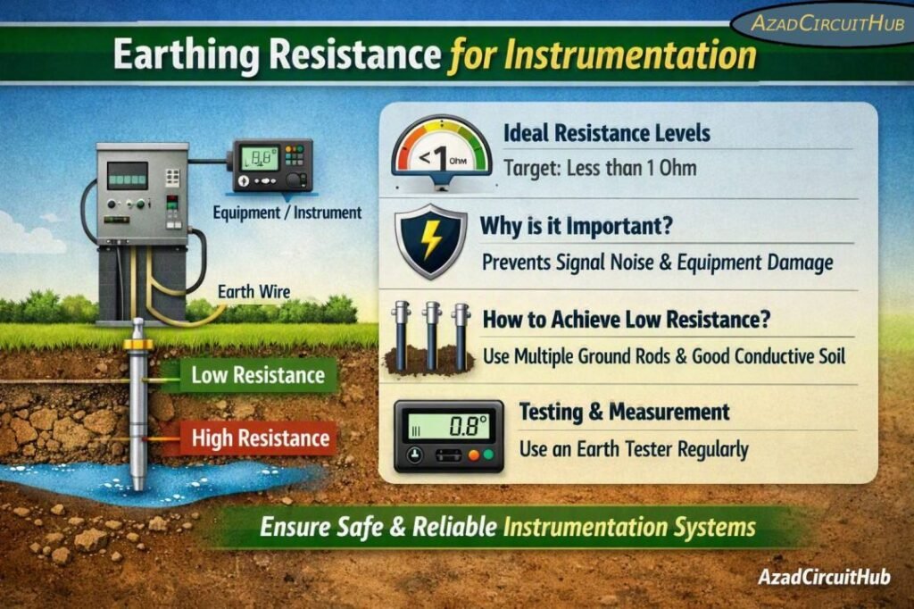
Table of Contents
Table of Contents
Recommended Earthing Resistance for Instrumentation
There is no single resistance value that applies to every instrumentation installation. The required value depends on the system voltage, soil resistivity, fault-current level, plant grounding philosophy, and applicable standards.
| Application | Typical Design Target | Main Purpose |
|---|---|---|
| Instrumentation/control earth | ≤ 1–5 Ω | Stable reference and fault protection |
| Sensitive electronic equipment | ≤ 1 Ω preferred | Reduce noise and potential differences |
| Control room instrumentation | ≤ 1 Ω preferred | Improve signal integrity |
| PLC/DCS grounding | ≤ 1 Ω preferred | Reliable equipment reference |
| General industrial equipment | ≤ 5 Ω | Protective earthing |
| Substation grounding grid | Site-specific | Personnel and equipment safety |
| Lightning protection earth | Site-specific | Safe discharge of lightning current |
These values are engineering targets rather than universal code limits. The final design should always follow the project specification, local electrical regulations, and the requirements of the equipment manufacturer.
Why Earthing Resistance Matters in Instrumentation
Sensitive instruments can operate with very small electrical signals. A small unwanted voltage between two grounding points can therefore become significant when compared with a 4–20 mA signal, thermocouple output, RTD signal, or communication reference.
High grounding resistance can also increase the voltage rise of an earth electrode during a fault or surge. A lower impedance grounding network helps provide a more stable reference and improves the discharge path for unwanted currents.
However, resistance is only one part of grounding performance. At higher frequencies, inductance and conductor arrangement become increasingly important. This is why a short, direct bonding connection can perform better for high-frequency noise than a long conductor with a similar DC resistance.
Instrument Earthing vs Protective Earthing
Instrumentation systems commonly use two related but different grounding concepts.
| Grounding Type | Typical Connection | Primary Function |
|---|---|---|
| Protective earth (PE) | Equipment enclosure to plant earth grid | Personnel safety |
| Instrument earth | Instrument reference/grounding network | Signal stability and noise control |
| Functional earth | Electronic equipment reference | Equipment operation |
| Shield/drain grounding | Cable shield to designated earth point | EMI reduction |
| Lightning earth | Lightning protection system | Surge current discharge |
Protective earthing should not be disconnected simply to solve an instrumentation noise problem. A better approach is to review the grounding topology, cable shielding, bonding, isolation, and potential ground loops.
For a complete grounding arrangement, see our guide to the instrument earthing system for practical details on grounding networks, instrument earth bars, bonding, and shield termination.
Typical Earthing Resistance Values for Control Systems
A practical project specification may establish different targets for different parts of an industrial facility.
| Equipment/System | Common Target | Design Consideration |
|---|---|---|
| PLC panel | ≤ 1 Ω preferred | Avoid noisy shared return paths |
| DCS cabinet | ≤ 1 Ω preferred | Follow manufacturer grounding scheme |
| SCADA equipment | ≤ 1 Ω preferred | Protect communication interfaces |
| Instrument junction box | ≤ 5 Ω | Ensure effective bonding |
| Field transmitters | Plant earth dependent | Use approved shield/earth arrangement |
| Control room earth bar | ≤ 1 Ω preferred | Low impedance bonding |
| Instrument cable shields | Project-specific | Usually grounded according to signal type |
The target should not be selected only because a particular number is commonly used. The grounding system must be evaluated as a complete network.
How to Measure Instrumentation Earthing Resistance
The three-point fall-of-potential method is commonly used for measuring earth electrode resistance. The electrode under test is separated from auxiliary current and potential electrodes, and the test instrument measures the resulting resistance.
For larger plants, clamp-on testing and other methods may also be used where the grounding arrangement allows them.
| Test Method | Typical Use | Important Point |
|---|---|---|
| 3-point fall-of-potential | Individual earth electrode | High accuracy when properly performed |
| 4-point soil testing | Soil resistivity survey | Used during grounding system design |
| Clamp-on test | Multiple connected earth paths | Requires suitable parallel grounding paths |
| Selective testing | Individual electrode in a network | Useful where disconnection is undesirable |
Before testing, inspect the grounding conductor, connections, earth pits, test links, corrosion, and mechanical joints. A low reading from a defective test setup should not be accepted without verification.
Soil Resistivity and Earth Resistance
Soil resistivity is one of the main factors affecting the performance of an earth electrode. Dry sand, rocky soil, and compacted ground can have much higher resistivity than moist clay or other conductive soils.
| Soil Condition | Relative Resistivity | Effect on Earthing |
|---|---|---|
| Moist clay | Low | Usually favorable |
| Wet soil | Low | Good electrode performance |
| Loam | Moderate | Generally suitable |
| Dry sand | High | Requires more electrode length/area |
| Rocky soil | Very high | Difficult grounding conditions |
During a new plant project, a soil resistivity survey should ideally be performed before finalizing the grounding electrode design. Multiple rods, buried grids, horizontal conductors, or other grounding electrodes may be required where soil conditions are poor.
Grounding Conductors for Instrumentation
The grounding conductor must be mechanically strong, corrosion-resistant, and adequately sized for the intended fault or bonding duty. Copper conductors are widely used, although other materials may be permitted by the applicable standard and project specification.
| Grounding Component | Typical Consideration |
|---|---|
| Instrument earth conductor | Sized according to design and applicable code |
| Panel bonding conductor | Must provide reliable protective bonding |
| Cable shield drain | Usually based on signal and EMC requirements |
| Earth grid conductor | Designed for fault current and thermal withstand |
| Equipment bonding jumper | Sized according to protective earthing requirements |
Conductor size should not be selected from resistance alone. Fault current, clearing time, mechanical strength, corrosion, installation method, and applicable electrical standards also need to be considered.
For fast conductor selection, use our earth cable size calculator to estimate an appropriate cable size before checking the final selection against the applicable standard and project requirements.
How to Reduce High Earthing Resistance
If an earth electrode produces an excessively high reading, several engineering measures can improve its performance.
- Increase the electrode length where soil conditions allow.
- Install additional electrodes with suitable spacing.
- Use a grounding grid or buried horizontal conductor.
- Improve electrode connections and remove corrosion.
- Locate electrodes in more conductive soil where practical.
- Use approved ground-enhancement materials when permitted by the project.
- Verify that the test method and auxiliary electrode spacing are correct.
Simply adding several rods very close together may provide less improvement than expected because their effective areas overlap. Proper electrode spacing and soil conditions are important.
Instrument Grounding and Ground Loops
Ground loops are a common source of instrumentation problems. They can produce unwanted circulating currents between equipment connected to different grounding points.
Symptoms can include unstable analog readings, noisy 4–20 mA signals, communication errors, and interference on control system inputs.
| Problem | Possible Cause | Corrective Action |
|---|---|---|
| Analog signal fluctuation | Ground potential difference | Review grounding topology |
| 50/60 Hz noise | Ground loop | Check shield and reference connections |
| Communication errors | Poor bonding/EMI | Improve EMC grounding |
| Transmitter noise | Shield termination issue | Follow manufacturer recommendation |
| Panel interference | Poor separation | Separate power and signal wiring |
A common mistake is to connect cable shields at multiple points without considering the signal type and EMC design. Shield grounding should follow the instrument manufacturer and project grounding philosophy.
Standards and Design Considerations
Instrumentation grounding may involve several standards depending on the facility and application. IEC 60364 provides requirements related to electrical installations and protective measures, while IEC 61000 series standards address electromagnetic compatibility. IEC 62305 is relevant where lightning protection is involved.
IEEE 1100 is also widely referenced for grounding and power-quality practices for sensitive electronic equipment. Industrial projects may additionally have owner specifications that establish specific resistance targets.
The important point is that a stated value such as 1 Ω or 5 Ω should be treated as a project design requirement only when supported by the applicable specification or engineering study.
Practical Instrumentation Earthing Checklist
Before commissioning an instrumentation grounding system, verify the following:
- Earth electrodes have been installed according to the approved design.
- Earth resistance has been tested using an appropriate method.
- Grounding conductors are correctly sized and identified.
- Instrument and protective earth arrangements are clearly defined.
- Control panels are properly bonded to the plant grounding network.
- Cable shields are terminated according to the signal and EMC requirements.
- Ground loops have been checked.
- Earth bars and connections are accessible for inspection.
- Grounding joints are protected against corrosion.
- Test results are recorded and compared with project requirements.
Frequently Asked Questions
What is a good earthing resistance for instrumentation?
A value of 1 Ω or less is often preferred for sensitive instrumentation and control systems, while 5 Ω is commonly used as a practical target for general industrial grounding. The actual requirement depends on the project specification, equipment manufacturer, soil conditions, and applicable standards.
Is 5 ohms good for instrumentation grounding?
A 5 Ω reading may be acceptable for some industrial installations, but it should not automatically be considered suitable for every instrumentation system. Sensitive PLC, DCS, control, and measurement systems may have tighter project requirements, such as 1 Ω or less.
How do you test instrumentation earth resistance?
The fall-of-potential method is commonly used for testing an individual earth electrode. The test should be performed with suitable auxiliary electrodes and adequate spacing. The grounding arrangement and test method should be reviewed before accepting the measured value.
Does low earth resistance eliminate instrument noise?
No. Low earth resistance alone does not eliminate instrumentation noise. Ground loops, poor shield termination, electromagnetic interference, cable routing, bonding, and ground potential differences can still cause signal problems.
What causes high earth resistance?
High earth resistance can result from high soil resistivity, dry ground, inadequate electrode length, poor connections, corrosion, insufficient electrode spacing, or an incorrect test setup. Soil testing and inspection can help identify the actual cause.
A properly designed grounding network is essential for safe and reliable industrial instrumentation. The goal is not simply to achieve the lowest possible resistance, but to provide a safe, stable, and low-impedance grounding and bonding system that supports both personnel protection and accurate signal performance.
For a deeper understanding of grounding layouts, instrument earth bars, shield grounding, and control-system bonding, explore our instrument earthing system guide.
Get new guides in your feed. Follow Electrical Insights on LinkedIn for new electrical standards guides, calculators and design tips from Azad Circuit Hub.
#EarthingResistance, #InstrumentationEarthing, #InstrumentGrounding, #ElectricalEarthing, #GroundingSystems, #IECStandards, #IndustrialInstrumentation, #ControlSystems, #ElectricalEngineering, #InstrumentationEngineering
