
Earthing in Hazardous Areas: Design, Standards, Methods and Best Practices
Earthing in hazardous areas is a critical part of electrical safety where flammable gases, vapors, liquids, dust, or combustible materials may create an explosive atmosphere. A properly designed grounding system helps control touch voltage, dissipate fault current, reduce static electricity, and provide a reliable path for protective devices to operate.
In industrial facilities such as oil and gas plants, refineries, chemical plants, fuel stations, pharmaceutical plants, and grain-processing facilities, ordinary grounding practices may not be sufficient. The earthing system must work together with hazardous-area classification, bonding, equipment selection, fault protection, lightning protection, and explosion-protection methods.
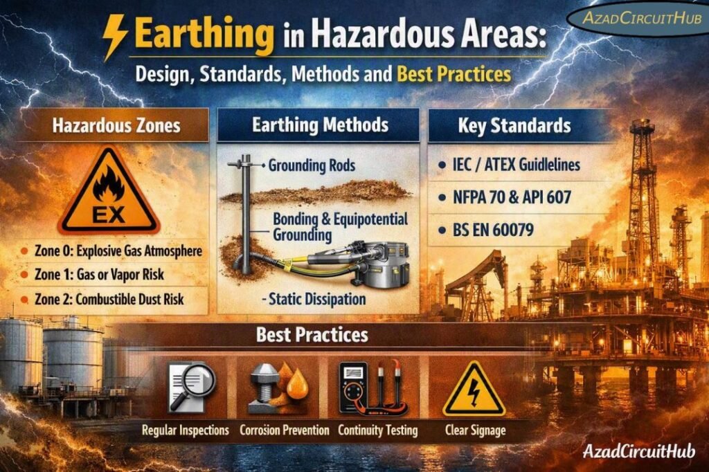
Table of Contents
Table of Contents
Quick Reference: Earthing in Hazardous Areas
| Item | Typical Requirement |
|---|---|
| Main purpose | Fault-current path, touch-voltage control, bonding and static dissipation |
| Common hazardous locations | Refineries, chemical plants, fuel terminals, gas plants, paint plants |
| Main standards | IEC 60079 series, IEC 60364, NFPA 70/NEC, IEEE 80 where applicable |
| Equipment bonding | Required for exposed conductive parts and relevant metallic systems |
| Static control | Bonding and grounding of conductive equipment and process systems |
| Intrinsically safe circuits | Follow the applicable IEC 60079-11 design and installation requirements |
| Earth conductor | Sized according to applicable electrical code and fault conditions |
| Earth electrodes | Ground rods, grids, tapes, plates or building foundation electrodes |
| Hazardous-area equipment | Must maintain the required explosion-protection concept |
| Key design principle | Prevent dangerous potential differences and ignition sources |
Why Earthing Is Important in Hazardous Locations
The primary purpose of earthing is to keep exposed conductive parts close to earth potential and provide a controlled path for fault current. In a hazardous location, this becomes even more important because an electrical fault, static discharge, or unwanted spark can potentially ignite an explosive atmosphere.
Earthing in hazardous areas normally addresses several risks:
- Electric shock from exposed metalwork
- Fault current through equipment enclosures
- Static charge accumulation
- Potential differences between metallic equipment
- Lightning-related voltage rise
- Electrical interference and unwanted circulating currents
- Faults involving cables, motors, instruments, and process equipment
A grounding system should therefore not be viewed simply as a connection to an earth rod. It is a complete network of protective conductors, bonding connections, earth electrodes, equipment grounding conductors, and equipotential connections.
Hazardous Area Classification and Grounding
Before designing earthing in hazardous areas, the location should be classified according to the type and duration of the explosive atmosphere.
IEC hazardous-area classification commonly uses Zones for gas, vapor, and mist hazards.
| Classification | General Meaning | Example |
|---|---|---|
| Zone 0 | Explosive gas atmosphere present continuously or for long periods | Inside certain process vessels |
| Zone 1 | Explosive atmosphere likely during normal operation | Around process equipment |
| Zone 2 | Explosive atmosphere not likely during normal operation, but possible briefly | Areas near flanges or vents |
| Zone 20 | Combustible dust atmosphere continuously or for long periods | Inside some dust-handling equipment |
| Zone 21 | Combustible dust atmosphere likely during normal operation | Dust-processing areas |
| Zone 22 | Dust atmosphere unlikely during normal operation but possible briefly | Areas around dust equipment |
The area classification itself does not mean that every earthing connection must use a separate earth electrode. Instead, the complete installation must provide effective protective bonding and comply with the applicable electrical and hazardous-location standards.
Equipotential Bonding in Hazardous Areas
Equipotential bonding is one of the most important parts of earthing in hazardous areas. Metallic objects that could develop different electrical potentials should be effectively bonded where required.
Typical items include:
- Motor frames
- Electrical enclosures
- Cable glands and metallic cable systems
- Structural steel
- Process vessels
- Storage tanks
- Metallic pipes
- Cable trays
- Ladders and platforms
- Instrument enclosures
- Metallic ducts
- Skids and packaged equipment
The objective is to minimize the voltage difference between conductive objects. This is particularly important where static electricity or fault current could otherwise produce a spark.
| Metallic Item | Typical Bonding Consideration |
|---|---|
| Motor frame | Protective earth connection |
| Electrical panel | PE connection to grounding system |
| Cable tray | Bond sections and provide continuity |
| Process piping | Bond where required by design and standards |
| Storage tank | Bonding and grounding based on process and lightning/static requirements |
| Instrument enclosure | Protective/equipotential bonding as applicable |
| Structural steel | Connect to the plant bonding network where required |
| Skid equipment | Bond metallic components to the plant grounding system |
Earthing of Electrical Equipment
Electrical equipment installed in a hazardous area must have the appropriate explosion-protection method for its classified location. Grounding does not make incorrectly rated equipment safe for a hazardous area.
For example, Ex d, Ex e, Ex i, Ex p and other protection concepts have different installation requirements. Cable entries, glands, enclosures, barriers, terminals, and bonding arrangements must be selected according to the equipment certification and installation standard.
Protective earth conductors should have adequate mechanical protection and fault-current capacity. Connections should also be protected against corrosion, loosening, and mechanical damage.
Protective Earth and Fault Current
During an insulation fault, the protective conductor should provide a sufficiently low-impedance path to allow the protective device to disconnect the faulty circuit within the required time.
A simplified relationship is:
Iᶠ ≈ V₀ / Zₛ
Where:
- Iᶠ = prospective fault current
- V₀ = nominal voltage to earth
- Zₛ = earth fault loop impedance
The actual calculation should follow the applicable installation standard and system configuration.
Instrument Earthing in Hazardous Areas
Instrumentation requires special attention because process instruments often operate with low-energy signals and sensitive electronics. Grounding errors can introduce noise, signal instability, ground loops, or unwanted potential differences.
Depending on the system design, instrument grounding may include protective earth, functional earth, shield grounding, intrinsic safety barriers, and equipotential bonding.
For instrumentation and control systems, avoid assuming that every instrument shield should be grounded at both ends. Shield termination depends on the signal type, EMC requirements, cable design, and manufacturer’s instructions.
For a dedicated guide to instrumentation grounding arrangements, use instrument earthing system to understand practical grounding methods, bonding, shield termination, and common installation mistakes.
Intrinsically Safe Circuits
Intrinsic safety is widely used in hazardous locations because it limits electrical and thermal energy to levels that cannot ignite the specified explosive atmosphere under defined conditions.
Grounding becomes part of the overall intrinsic safety design where grounded barriers, IS interfaces, or associated apparatus are used.
Important considerations include:
- Follow the certified system design.
- Use the specified barriers or isolators.
- Maintain segregation between IS and non-IS circuits.
- Maintain required bonding and earth continuity.
- Follow cable and termination requirements.
- Do not introduce unauthorized grounding connections.
- Check the entity or system parameters where applicable.
The installation should be verified against the applicable equipment certificates and IEC 60079 requirements rather than relying on a generic grounding arrangement.
Cable Glands, Screens and Armouring
Cable systems can form an important part of the equipotential bonding network. Metallic armour, screens, glands, and cable trays should be installed according to the cable design and hazardous-area requirements.
For armoured cables, the gland arrangement must maintain the required environmental sealing, mechanical protection, and electrical continuity. Certified hazardous-area glands should be used where required.
| Cable Component | Main Purpose |
|---|---|
| Protective conductor | Fault-current path |
| Cable armour | Mechanical protection and, where designed, bonding/fault path |
| Metallic screen | EMC/noise control and signal shielding |
| Ex gland | Maintains required hazardous-area protection |
| Cable tray | Support and possible bonding path when designed accordingly |
Cable armour should not automatically be treated as an adequate protective conductor. Its suitability must be verified based on material, cross-sectional area, fault current, installation method, and applicable code.
Earth Cable Sizing
The protective earthing conductor must be sized according to the governing standard and installation conditions. Factors can include prospective fault current, fault-clearing time, conductor material, installation temperature, and permissible conductor stress.
For preliminary cable selection, our earth cable size calculator can help estimate an appropriate conductor size before the final design is checked against the applicable electrical standard.
The final design should always verify short-circuit withstand, thermal performance, mechanical protection, voltage drop where relevant, and local code requirements.
Static Electricity Control
Static electricity is a significant concern in facilities handling flammable liquids, gases, powders, and other combustible materials.
Static charge can accumulate when materials move through pipes, hoses, filters, conveyors, or process equipment. If the charge is suddenly discharged, the resulting spark may become an ignition source.
Grounding and bonding can reduce this risk by providing a controlled path for charge dissipation.
Typical measures include:
- Bonding tanker connections
- Grounding storage tanks
- Bonding conductive process equipment
- Using conductive or dissipative hoses where required
- Maintaining electrical continuity across isolated sections
- Verifying grounding connections periodically
Static-control requirements should be assessed according to the process, material, flow conditions, equipment design, and applicable standards.
Lightning Protection and Hazardous Areas
Lightning protection must be coordinated with the plant earthing and bonding system. A lightning event can produce very high transient currents and dangerous potential differences.
For hazardous facilities, the design may include:
- Air termination systems
- Down conductors
- Earth electrodes
- Equipotential bonding
- Surge protective devices
- Bonding of exposed metallic structures
The lightning protection system should be designed as a coordinated system rather than adding random earth rods around hazardous equipment.
Testing and Inspection
A grounding system is only effective if its connections remain electrically continuous throughout its service life.
Routine inspection should consider:
| Inspection Item | What to Check |
|---|---|
| Earth connections | Tightness, corrosion and physical condition |
| Bonding conductors | Continuity and mechanical damage |
| Cable glands | Correct type, sealing and certification |
| Cable armour | Continuity and termination |
| Equipment PE | Secure connection |
| Earth electrodes | Condition and measured resistance where applicable |
| Instrument grounding | Correct termination and segregation |
| Static bonding | Continuity of required bonding paths |
| Lightning system | Down conductors, bonds and electrodes |
Earth resistance measurements alone do not prove that the entire protective bonding system is satisfactory. Continuity, impedance, conductor sizing, connection quality, and fault-clearing performance are also important.
Common Earthing Mistakes in Hazardous Areas
Several grounding practices can create problems even when an earth connection appears to be present.
Common mistakes include:
- Using uncertified cable glands in classified locations
- Leaving metallic equipment unbonded
- Assuming cable armour is always an adequate PE conductor
- Creating unnecessary grounding loops in instrumentation
- Ignoring corrosion at earth connections
- Mixing IS and non-IS circuits incorrectly
- Installing separate earth electrodes without proper system coordination
- Failing to verify protective conductor sizing
- Treating earth resistance as the only acceptance criterion
- Modifying certified equipment without considering its certification
A properly documented grounding design should identify the protective earth network, bonding points, earth electrodes, instrument grounding, cable systems, and testing requirements.
Key Design Checklist
Before commissioning an industrial hazardous-area installation, verify:
- Hazardous zones are correctly identified.
- Equipment has the appropriate hazardous-area certification.
- Protective conductors are correctly sized.
- Metallic equipment is bonded where required.
- Cable glands meet the installation requirements.
- Cable armour and screens are correctly terminated.
- Intrinsically safe circuits maintain required segregation.
- Static bonding requirements are satisfied.
- Lightning protection is coordinated with the grounding system.
- Earth and bonding connections are inspected and tested.
- Grounding drawings and test records are maintained.
FAQs About Earthing in Hazardous Areas
1. Why is earthing required in hazardous areas?
Earthing provides a controlled path for fault current, reduces touch voltage, supports equipotential bonding, and helps dissipate static charge. These measures reduce the possibility of electrical faults or static discharges becoming dangerous ignition sources.
2. Do hazardous areas need a separate earth electrode?
Not necessarily. A hazardous-area installation normally needs an effective grounding and bonding system, but a separate electrode is not automatically required for every classified area. The arrangement should follow the electrical system design and applicable IEC, NEC, or local requirements.
3. How do you ground intrinsically safe equipment?
Intrinsically safe equipment should be grounded according to its certified system design and the applicable hazardous-area standard. Barriers, isolators, bonding, cable screens, and segregation must all be considered rather than adding arbitrary earth connections.
4. Should cable armour be earthed in hazardous areas?
Where metallic armour is used, it generally needs appropriate bonding and termination as part of the protective system. The gland and termination method must comply with the cable design, equipment certification, and applicable hazardous-area requirements.
5. Is low earth resistance enough for a hazardous-area grounding system?
No. Low earth resistance alone does not demonstrate that the installation is safe. Protective conductor sizing, bonding continuity, fault-loop impedance, connection quality, static control, equipment certification, and protective-device operation must also be verified.
For engineers working on industrial electrical systems, instrument earthing system provides a useful reference when designing grounding and bonding arrangements for control and instrumentation installations. A coordinated approach helps avoid noise problems while maintaining electrical safety.
A reliable grounding network is ultimately about more than achieving a low resistance reading. Effective bonding, correct protective conductors, suitable hazardous-area equipment, proper cable termination, and regular inspection must work together to control electrical and ignition hazards.
Get new guides in your feed. Follow Electrical Insights on LinkedIn for new electrical standards guides, calculators and design tips from Azad Circuit Hub.
#EarthingInHazardousAreas, #HazardousAreaEarthing, #ElectricalEarthing, #GroundingSystems, #HazardousAreaSafety, #IECStandards, #ElectricalSafety, #ExEquipment, #GroundingDesign, #IndustrialSafety
