
Cable Tray Fill Chart: Maximum Fill by Tray Width (NEC 392)
A properly sized cable tray keeps conductors organized, improves heat dissipation, and leaves enough room for installation and maintenance. The NEC does not set one universal cable tray width for every installation. Instead, cable tray sizing depends on the cable type, number of conductors, cable dimensions, and the usable interior area of the tray.
This cable tray fill chart explains the practical fill limits used under NEC Article 392, with examples for common tray widths and depths. It also shows how to convert the NEC percentage limits into usable square inches when selecting a tray.
Cable Tray Fill Chart at a Glance
For most cable tray installations, the first step is determining the allowable fill percentage. NEC Article 392.22 provides the rules for calculating the maximum cable area inside the tray.
| Cable arrangement | Typical NEC maximum fill | Main sizing basis |
|---|---|---|
| Single-conductor cables 4/0 AWG and larger | 50% | Interior tray area |
| Multiconductor cables 4/0 AWG and larger | 40% | Interior tray area |
| Multiconductor cables smaller than 4/0 AWG | 40% | Interior tray area |
| Mixed single and multiconductor cables | 40% | Applicable cable area rules |
| Example 4 in × 4 in tray at 40% | 6.40 sq. in. | 16 sq. in. × 40% |
| Example 4 in × 4 in tray at 50% | 8.00 sq. in. | 16 sq. in. × 50% |
The exact requirement should always be checked against the applicable NEC edition, cable construction, tray type, and installation conditions.
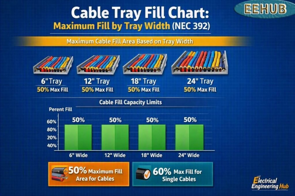
Table of Contents
Table of Contents
NEC Cable Tray Fill Requirements
NEC Article 392 covers cable trays and includes requirements for cable installation, ampacity, grounding, support, and cable tray fill. Section 392.22 is particularly important because it establishes how much of the available tray area can be occupied by conductors.
The key point is that fill is based on area, not simply the number of cables. A tray that looks large enough may still be undersized if the combined cross-sectional area of the cables exceeds the permitted limit.
For example, a 4-inch-wide tray with a 4-inch usable depth has a theoretical interior area of:
4 in × 4 in = 16 sq. in.
At 40% fill:
16 × 0.40 = 6.40 sq. in.
At 50% fill:
16 × 0.50 = 8.00 sq. in.
These calculations are the foundation of a cable tray fill chart.
Maximum Cable Fill by Tray Width
The following table provides practical reference values. It assumes the stated width and usable interior depth and does not account for fittings, sidewall reductions, special cable arrangements, or manufacturer-specific dimensions.
| Tray width | 3 in depth | 4 in depth | 6 in depth | 8 in depth |
|---|---|---|---|---|
| 4 in | 4.80 sq. in. | 6.40 sq. in. | 9.60 sq. in. | 12.80 sq. in. |
| 6 in | 7.20 sq. in. | 9.60 sq. in. | 14.40 sq. in. | 19.20 sq. in. |
| 12 in | 14.40 sq. in. | 19.20 sq. in. | 28.80 sq. in. | 38.40 sq. in. |
| 18 in | 21.60 sq. in. | 28.80 sq. in. | 43.20 sq. in. | 57.60 sq. in. |
| 24 in | 28.80 sq. in. | 38.40 sq. in. | 57.60 sq. in. | 76.80 sq. in. |
| 30 in | 36.00 sq. in. | 48.00 sq. in. | 72.00 sq. in. | 96.00 sq. in. |
| 36 in | 43.20 sq. in. | 57.60 sq. in. | 86.40 sq. in. | 115.20 sq. in. |
These figures use the 40% fill limit. They are useful for preliminary sizing, but the actual tray dimensions should be verified using the manufacturer’s inside dimensions.
Need a faster way to check your tray size? Use our cable tray fill calculator to calculate allowable cable area from tray width, depth, and the applicable fill percentage.
How to Calculate Cable Tray Fill
The basic calculation is straightforward:
Maximum allowable cable area = Tray usable area × permitted fill percentage
First calculate the tray’s usable interior area:
Tray area = Width × Usable depth
Then multiply that value by the applicable NEC fill percentage.
Example
Suppose a project uses a 12-inch-wide tray with a 4-inch usable depth.
Tray area = 12 × 4 = 48 sq. in.
Using a 40% fill limit:
Maximum cable area = 48 × 0.40 = 19.20 sq. in.
Therefore, the combined cross-sectional area of the cables should not exceed 19.20 square inches under that particular fill calculation.
The cable manufacturer’s published outside diameter is important because cable area must be determined from the actual cable dimensions rather than the nominal conductor size alone.
40% vs. 50% Cable Tray Fill
One of the most common mistakes in tray sizing is applying the same fill percentage to every cable arrangement. NEC Article 392 distinguishes between different cable configurations.
For example, certain single-conductor cable installations can use a 50% area limit, while multiconductor cable installations are commonly calculated using a 40% limit. Mixed cable arrangements can also have specific requirements.
| Fill percentage | Example tray area | Maximum cable area |
|---|---|---|
| 30% | 48 sq. in. | 14.40 sq. in. |
| 40% | 48 sq. in. | 19.20 sq. in. |
| 50% | 48 sq. in. | 24.00 sq. in. |
Do not automatically use 50% simply because physical space is available. The applicable NEC section and cable arrangement determine which limit should be used.
Cable Tray Width Selection
Cable tray width should provide enough room for the calculated cable area while also considering future expansion, cable routing, installation access, and the manufacturer’s requirements.
Common tray widths include 6, 12, 18, 24, 30, and 36 inches. Larger trays are often selected for industrial power distribution where several circuits share the same route.
For example, if your calculated cable area is 17 sq. in., a 12-inch × 4-inch tray provides 19.2 sq. in. at 40% fill. However, selecting the smallest possible tray is not always the best engineering choice. Future circuits and installation practicality may justify a wider tray.
For a quick comparison of cable area and available tray capacity, a cable tray fill calculator can reduce manual calculations and help check several tray sizes quickly.
Cable Tray Fill Calculation Example
Consider a 24-inch-wide tray with a usable depth of 4 inches.
Interior area = 24 × 4 = 96 sq. in.
At 40%:
96 × 0.40 = 38.40 sq. in.
If the total calculated cable cross-sectional area is 31 sq. in., the tray remains below the 40% area limit.
If the cable area is 42 sq. in., the tray exceeds the 40% limit even though more than half of the physical tray appears empty.
This demonstrates why visual estimation is unreliable. The correct approach is to calculate the total cable area and compare it with the allowable tray area.
Important Factors Beyond Tray Fill
Cable tray sizing is not determined by fill alone. A complete design should also consider:
- Cable ampacity and adjustment factors
- Ambient temperature
- Number of current-carrying conductors
- Cable outside diameter
- Cable weight and tray load capacity
- Tray support span
- Cable separation requirements
- Voltage level
- Grounding and bonding
- Future cable additions
- Manufacturer’s installation instructions
Heat dissipation is especially important for heavily loaded power cables. A tray that satisfies the physical fill requirement may still require additional engineering review for ampacity and thermal conditions.
Cable Tray Fill vs. Conduit Fill
Cable tray and conduit use different sizing methods. Conduit fill is generally based on the number of conductors and the percentage of the raceway’s internal area permitted by NEC Chapter 9, Table 1. Cable tray sizing is governed primarily by Article 392 and depends on cable arrangement and available tray area.
| Feature | Cable tray | Conduit |
|---|---|---|
| Primary NEC article | Article 392 | Chapter 9 and applicable raceway articles |
| Main sizing factor | Cable area and tray area | Conductor area and raceway area |
| Typical fill basis | 40% or 50%, depending on arrangement | Varies by conductor count |
| Cable arrangement | Open installation | Enclosed raceway |
| Heat dissipation | Generally better | More confined |
Understanding this difference prevents engineers and electricians from applying conduit fill percentages directly to cable tray calculations.
Quick Cable Tray Sizing Checklist
Before selecting a tray, verify these points:
- Identify the cable type and construction.
- Obtain the actual outside diameter of each cable.
- Calculate the cross-sectional area of each cable.
- Add the areas of all cables to be installed.
- Determine the applicable NEC fill percentage.
- Calculate the tray’s usable interior area.
- Compare allowable cable area with total cable area.
- Check ampacity, temperature, loading, and support requirements.
- Allow for practical installation and future expansion.
- Confirm the final selection with the tray manufacturer’s data.
If you regularly size trays for industrial or commercial projects, our cable tray fill calculator provides a convenient way to check tray dimensions and allowable cable area without repeating the calculation manually.
Frequently Asked Questions
What is the maximum cable tray fill under NEC 392?
The permitted fill depends on the cable arrangement. A 40% area limit is commonly used for multiconductor cable installations, while certain single-conductor cable installations can use 50%. The specific requirements of NEC 392.22 should be applied to the installation.
How do you calculate cable tray fill?
Multiply the usable tray width by its usable interior depth to find the available area. Then multiply that area by the applicable fill percentage. Finally, compare the result with the combined cross-sectional area of the installed cables.
Does cable tray fill include the cable insulation diameter?
Yes. Cable area calculations are based on the cable’s overall dimensions, including insulation and jacket, rather than only the conductor diameter. Manufacturer data is the best source for accurate cable outside diameter.
Can I use 50% fill for every cable tray?
No. The 50% limit is not a universal value. The applicable percentage depends on the cable type and arrangement covered by NEC Article 392. Using an incorrect percentage can result in an improperly sized tray.
Does a wider cable tray always solve a fill problem?
A wider tray increases available area, but it does not automatically solve every design issue. Cable ampacity, heat dissipation, tray loading, support spacing, grounding, and installation requirements must also be evaluated.
Final Takeaway
A reliable cable tray fill chart starts with the actual tray dimensions and the correct NEC fill percentage. For a 40% calculation, multiply the usable tray width and depth by 0.40; for an applicable 50% calculation, multiply by 0.50. Then compare the allowable area with the total outside cross-sectional area of the cables.
Using the correct fill percentage is only one part of a complete cable tray design. Always verify cable ampacity, tray loading, support requirements, environmental conditions, and the latest applicable NEC requirements before final installation.
For projects involving multiple tray sizes or large cable groups, our cable tray fill calculator can make the sizing process faster while providing a quick check against manual calculations.
Get new guides in your feed. Follow Electrical Insights on LinkedIn for new electrical standards guides, calculators and design tips from Azad Circuit Hub.
#CableTrayFillChart, #CableTray, #NEC392, #CableTraySizing, #ElectricalEngineering, #CableManagement, #NECStandards, #ElectricalInstallation, #CableTrayCapacity, #ElectricalDesign
