
Cable Shield Grounding & Cable Screening
Cable shield grounding and cable screening are important parts of a reliable instrumentation, automation, and control system. A cable shield helps reduce the effect of electromagnetic interference (EMI), radio-frequency interference (RFI), and electrical noise on sensitive signals.
Poor shield termination can create another problem. Instead of reducing interference, the shield may become a path for unwanted current or introduce a ground loop. The correct method therefore depends on the signal type, frequency, installation environment, and equipment design.
This guide explains practical methods for shield grounding, cable screening, shield termination, grounding at one or both ends, and common installation mistakes.
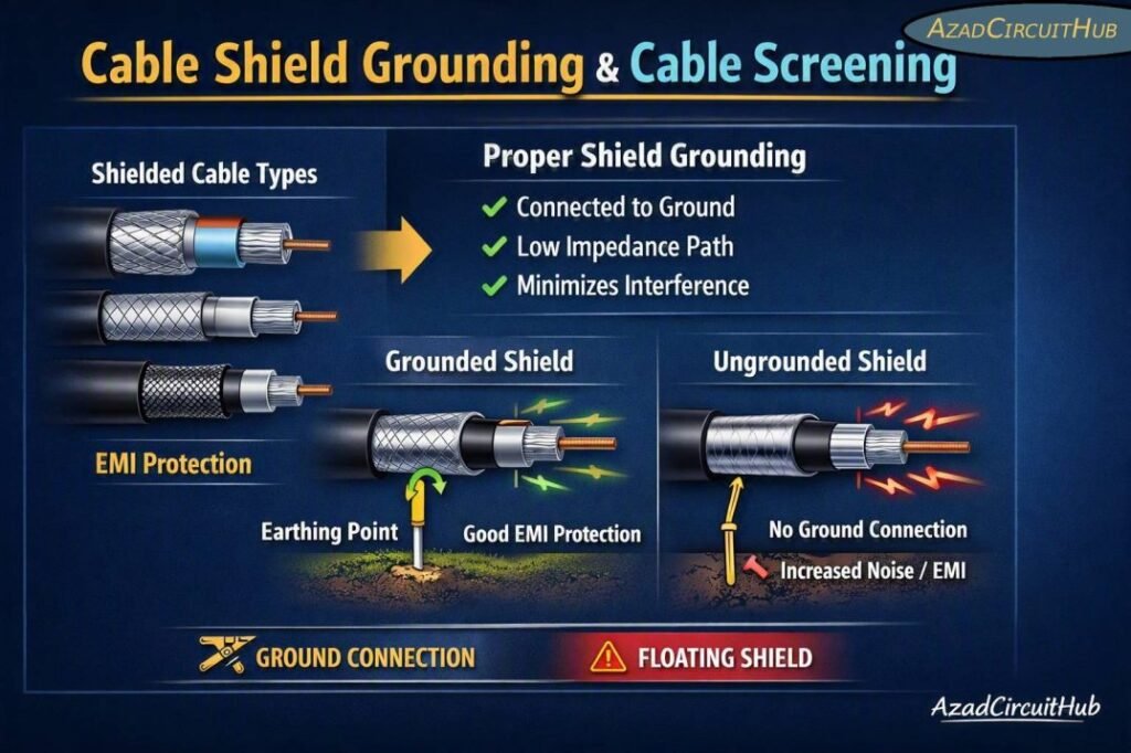
Table of Contents
Table of Contents
Cable Shield Grounding Quick Reference
| Application | Typical shield connection | Main purpose | Key consideration |
|---|---|---|---|
| Analog 4–20 mA signal | Usually one end for low-frequency systems | Reduce noise and ground loops | Follow system design |
| Thermocouple cable | Usually instrument/control-system design dependent | Protect low-level signals | Avoid unwanted ground paths |
| High-frequency communication | Often both ends with suitable EMC termination | Control high-frequency noise | 360° shield bonding is preferred |
| VFD motor cable | Both ends | Reduce EMI and common-mode noise | Use full-circumference termination |
| RS-485/industrial communication | Usually according to network specification | Improve EMC performance | Maintain shield continuity |
| Intrinsically safe circuits | According to hazardous-area design | EMC and safety | Follow IEC 60079 requirements |
| Control cabinet wiring | Bond shield to appropriate EMC reference | Reduce cabinet noise | Keep pigtails short |
What Is Cable Shielding?
Cable shielding is a conductive layer placed around one or more cable conductors. The shield can be made from copper braid, copper tape, aluminum foil, drain wire arrangements, or a combination of these materials.
The purpose is to reduce the amount of electrical or magnetic interference reaching the conductors inside the cable. It can also limit electromagnetic energy radiated from the cable.
Common shield constructions include:
- Copper braid
- Aluminum/polyester foil
- Copper tape
- Spiral copper shield
- Foil and braid combination
- Metallic armor with an additional EMC shield
The choice depends on the required shielding effectiveness, operating frequency, mechanical requirements, and installation environment.
Cable Shield Grounding vs Cable Screening
The terms shielding and screening are often used interchangeably. In practical electrical engineering, both describe methods used to protect signal circuits from electromagnetic interference.
Cable screening normally refers to the physical conductive layer around the signal conductors, while grounding describes how that conductive layer is connected to earth or the equipment reference.
| Term | Meaning |
|---|---|
| Cable screen | Conductive layer surrounding cable conductors |
| Cable shield | Another common term for the conductive screen |
| Drain wire | Conductor used to connect a foil shield |
| Shield termination | Physical connection between shield and grounding system |
| EMC bonding | Low-impedance connection intended to control electromagnetic interference |
| Protective earth | Safety conductor used for electrical protection |
| Signal reference | Reference potential used by electronic circuits |
A cable screen is only effective when its termination is designed correctly. A high-quality shield connected through a long wire pigtail may perform poorly at high frequencies.
How Cable Shield Grounding Works
Cable shield grounding provides a controlled path for interference currents. When an external electromagnetic field reaches a shielded cable, the shield can reduce the electric field coupled into the internal conductors.
At low frequencies, engineers may use a single-end shield connection to reduce the possibility of circulating ground-loop current. At higher frequencies, however, a shield bonded at both ends can provide better EMC performance because high-frequency currents need a low-impedance return path.
The correct approach should therefore not be selected from a single universal rule.
For industrial installations, consider:
- Signal frequency
- Cable length
- Noise source
- Equipment grounding arrangement
- Difference in ground potential
- Shield construction
- EMC requirements
- Manufacturer recommendations
Should a Cable Shield Be Grounded at One End or Both Ends?
This is one of the most common questions in instrumentation wiring.
For low-frequency analog signals, grounding the shield at one end has traditionally been used to minimize circulating currents caused by differences in ground potential. The shield is commonly terminated at the control-system or receiving-end panel.
For high-frequency interference, grounding or bonding the shield at both ends can provide better protection. This is especially important for drives, high-speed communications, and systems exposed to strong electromagnetic fields.
| Circuit type | Common approach | Reason |
|---|---|---|
| Low-frequency analog | Single-end termination may be used | Limits low-frequency circulating current |
| High-frequency signal | Both-end bonding often preferred | Provides low-impedance HF path |
| VFD output cable | Both ends | Controls conducted and radiated EMI |
| Ethernet/industrial Ethernet | Equipment-specific shield bonding | Maintains EMC performance |
| RS-485 | Follow network manufacturer’s specification | Prevents communication problems |
| Hazardous-area instrumentation | Follow approved system design | Safety and EMC requirements |
There is no universal “one end is always correct” rule. The equipment manufacturer’s instructions and the applicable installation standard should take priority.
Best Practice for Shield Termination
The physical termination is just as important as the grounding point.
A common mistake is to strip a long section of shield and connect it using a thin drain wire. This arrangement may work at low frequencies but can have significant impedance at higher frequencies.
For high-frequency EMC protection, a short and wide connection or 360-degree shield clamp provides a much better path.
Recommended shield termination practices
- Keep shield connections short.
- Avoid unnecessary shield pigtails.
- Use EMC cable glands where appropriate.
- Maintain shield continuity through junction boxes.
- Bond metallic cable glands to the appropriate enclosure.
- Separate noisy power cables from sensitive signal cables.
- Follow the cable manufacturer’s termination instructions.
- Use proper cabinet grounding and bonding.
For instrumentation projects, correct bonding should form part of the overall instrument earthing system, rather than being treated as an isolated cable detail.
Cable Screening for Analog Instrumentation
Analog signals such as 4–20 mA, RTD, thermocouple, and low-level voltage signals can be affected by electromagnetic noise.
Sources include:
- Variable frequency drives
- Motors
- Contactors
- Transformers
- Switching power supplies
- High-current busbars
- Welding equipment
- Power cables
- Radio transmitters
A screened twisted-pair cable is commonly used for many instrumentation circuits. Twisting reduces magnetic pickup, while the screen helps control electric-field interference.
For a 4–20 mA loop, the shield should be terminated according to the instrument and control-system design. The shield should not be treated as the signal return conductor.
Cable Shielding for VFD and Motor Applications
Variable frequency drives generate fast voltage transitions that can produce substantial common-mode and radiated electromagnetic interference.
A suitable shielded motor cable can reduce this interference when the shield is properly bonded at both the drive and motor ends.
| Installation feature | Recommended practice |
|---|---|
| Motor cable | Use suitable shielded VFD cable |
| Drive end | Use proper EMC shield termination |
| Motor end | Maintain shield continuity to motor frame |
| Cable gland | Use suitable EMC gland where required |
| Cable routing | Keep away from sensitive instrumentation |
| Parallel runs | Minimize long parallel signal/power runs |
| Shield connection | Prefer low-impedance termination |
A shield that is connected only through a long drain wire may not provide the same EMC performance as a properly terminated shield.
Cable Screening and Ground Loops
A ground loop can occur when a shield or circuit reference creates multiple conductive paths between equipment at different locations.
Ground-loop effects may appear as:
- 50/60 Hz hum
- Analog signal fluctuations
- Measurement errors
- Communication instability
- Unexpected noise on control signals
However, disconnecting shields at random is not a proper solution. The grounding architecture should first be reviewed.
Check whether the problem comes from:
- Ground potential differences
- Incorrect shield termination
- Poor bonding
- Multiple signal references
- Incorrect power-system grounding
- Damaged cable shields
For larger plants, shield grounding should be coordinated with the overall instrument earthing system so that signal grounding, protective bonding, and EMC requirements work together.
Shield Grounding in Control Panels
Control panels often contain both high-power and low-level circuits. Good internal segregation is therefore essential.
| Panel circuit | Typical installation approach |
|---|---|
| VFD wiring | Keep separated from analog signal wiring |
| 4–20 mA | Use suitable screened twisted pair |
| PLC I/O | Follow PLC manufacturer’s grounding guidance |
| Communication | Maintain cable shield continuity |
| AC power | Route separately from sensitive signals |
| Shield termination | Use designated EMC/shielding points |
Do not terminate every cable shield onto an arbitrary earth terminal. The panel’s grounding and EMC design should define where shields are connected.
Cable Shield Grounding in Hazardous Areas
Hazardous-area instrumentation requires additional care. Intrinsically safe circuits, associated apparatus, barriers, cable construction, segregation, and earthing arrangements must comply with the approved system design.
IEC 60079 series requirements are commonly relevant to electrical installations in explosive atmospheres. The exact arrangement depends on the protection concept, equipment certification, installation method, and project requirements.
Never modify an approved intrinsic-safety grounding arrangement simply to solve an apparent noise problem. Review the complete loop design first.
Shielding Materials and Their Performance
Different shield constructions provide different levels of protection.
| Shield type | Main advantage | Typical limitation |
|---|---|---|
| Foil shield | Good high-frequency electric-field coverage | Can be mechanically delicate |
| Copper braid | Strong mechanical construction | Coverage may vary |
| Foil + braid | Broad frequency protection | Higher cost |
| Copper tape | Excellent continuity when properly installed | More difficult termination |
| Spiral shield | Flexible cable construction | Less effective than full coverage in some applications |
For demanding industrial EMC environments, a combination of foil and braid may provide useful broadband protection.
Common Cable Screening Mistakes
Several installation practices can reduce shielding effectiveness.
1. Long shield pigtails
A long pigtail increases impedance and can reduce high-frequency shielding performance.
2. Poor cable gland selection
A conventional gland may not provide the EMC bonding required for a shielded cable.
3. Mixing signal and power cables
Long parallel runs beside VFD or high-current cables can increase electromagnetic coupling.
4. Using the shield as a signal conductor
The shield should not normally be used as the functional return conductor unless the circuit design specifically permits it.
5. Randomly grounding both ends
Both-end bonding can be beneficial for high-frequency EMC, but it can also create unwanted low-frequency currents in some systems. The complete grounding architecture matters.
Shield Grounding Checklist
Before commissioning a shielded instrumentation system, check the following:
- Confirm the cable type and shield construction.
- Verify shield continuity.
- Check the termination method.
- Keep high-frequency shield connections short.
- Confirm cable gland compatibility.
- Separate signal and power wiring.
- Check cabinet bonding.
- Verify the grounding design.
- Confirm hazardous-area requirements where applicable.
- Follow equipment manufacturer recommendations.
If shield bonding involves a protective conductor or grounding conductor, conductor sizing should also be checked using an appropriate earth cable size calculator based on the applicable electrical standard and fault conditions.
Cable Shield Grounding Standards and Guidance
No single standard covers every cable-screening application. Different parts of the installation may be governed by different standards.
| Standard or guidance | Relevance |
|---|---|
| IEC 61000 series | Electromagnetic compatibility and EMC practices |
| IEC 61000-5-2 | Earthing and cabling guidance for EMC |
| IEC 60079 series | Electrical installations in explosive atmospheres |
| IEC 60228 | Conductors of insulated cables |
| IEC 60364 series | Low-voltage electrical installations |
| Manufacturer specifications | Equipment-specific shield and grounding requirements |
Always verify the edition adopted by the project, local regulations, and equipment manufacturer.
Frequently Asked Questions
Should cable shielding be grounded at both ends?
It depends on the application. Both-end bonding is often effective for high-frequency EMC and VFD applications, while single-end termination may be used for some low-frequency analog circuits to reduce circulating currents.
What is the difference between cable shielding and grounding?
Cable shielding is the conductive layer around the cable conductors. Grounding or bonding defines how that shield is connected to the electrical reference, earth, or equipment structure.
What happens if a cable shield is not grounded?
An unconnected shield may provide limited protection because it does not have an effective path for interference currents. Its effectiveness depends on the frequency, cable construction, surrounding equipment, and overall EMC design.
Should a 4–20 mA cable shield be grounded at one end?
In many conventional instrumentation systems, the shield is terminated at one end, often at the control-system or receiving-end panel. However, the final arrangement should follow the instrument manufacturer’s instructions and project grounding philosophy.
Why is 360-degree shield termination used?
A 360-degree termination provides a low-impedance connection around the cable circumference. It is particularly useful for controlling high-frequency interference compared with a long, narrow shield pigtail.
Final Takeaway
Effective cable shield grounding is not simply a matter of connecting every shield to earth. The correct method depends on signal frequency, interference sources, cable construction, grounding architecture, equipment design, and applicable standards.
For low-frequency instrumentation, single-end shield termination can be useful in suitable systems. For high-frequency EMC applications and VFD motor cables, low-impedance bonding at both ends is often more effective. Good cable routing, shield continuity, proper glands, and cabinet bonding are equally important.
A well-designed screening arrangement protects sensitive instrumentation while reducing noise, communication faults, and measurement errors. It should always be considered as part of the complete instrument earthing system, rather than as a separate wiring detail.
Get new guides in your feed. Follow Electrical Insights on LinkedIn for new electrical standards guides, calculators and design tips from Azad Circuit Hub.
