
How to Calculate Cable Tray Fill NEC 392 | Step by Step
Cable tray systems must be sized correctly to prevent overcrowding, simplify maintenance, and comply with the National Electrical Code (NEC). Learning how to Calculate Cable Tray Fill helps engineers, electricians, and contractors select the right tray size before installation. It also reduces future expansion problems and improves cable management.
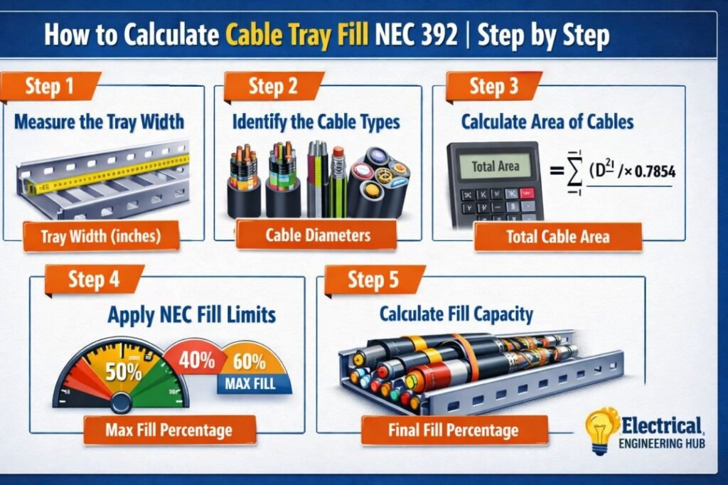
Table of Contents
Table of Contents
Before starting the calculation, use this quick reference.
| Quick Cable Tray Fill Guide | Value |
|---|---|
| Standard | NEC Article 392 |
| Main Objective | Determine allowable cable occupancy |
| Required Inputs | Tray Width, Cable Diameter, Cable Quantity, Cable Type |
| Common Tray Types | Ladder, Ventilated Trough, Solid Bottom, Wire Mesh |
| Related Standard | NEC 392.22 |
| Ampacity Consideration | NEC 392.80 |
| Step | Action |
|---|---|
| Step 1 | Identify cable type |
| Step 2 | Measure cable diameter |
| Step 3 | Count total cables |
| Step 4 | Calculate occupied area |
| Step 5 | Compare with allowable tray fill |
| Step 6 | Verify NEC 392.80 ampacity derating if required |
For faster calculations, use our Cable Tray Fill Calculator according to NEC to verify tray sizing before selecting cable tray dimensions.
Why It Is Important to Calculate Cable Tray Fill
When designers Calculate Cable Tray Fill correctly, they avoid several installation problems including cable overheating, damaged insulation, difficult maintenance, and future expansion limitations.
NEC Article 392 provides rules for different cable types because single conductors, multiconductor cables, and large power cables occupy tray space differently.
Incorrect tray sizing may result in:
| Problem | Effect |
|---|---|
| Overfilled tray | Difficult cable pulling |
| Poor ventilation | Higher cable temperature |
| Limited maintenance space | Longer shutdown time |
| Future cable additions impossible | Tray replacement required |
| Excess cable pressure | Insulation damage |
Proper tray fill also improves airflow around conductors, which directly influences cable ampacity.
NEC Articles Used for Cable Tray Fill
Several NEC sections work together during tray design.
| NEC Section | Purpose |
|---|---|
| NEC 392.22 | Cable tray fill requirements |
| NEC 392.80 | Cable ampacity and derating |
| NEC Chapter 9 | Conductor dimensions |
| NEC Article 310 | Conductor ampacity |
Many designers focus only on tray width, but cable ampacity must also be verified after tray fill is complete.
How to Calculate Cable Tray Fill as per NEC 392
Step 1 – Identify the Cable Type
The first step is identifying which cables will be installed.
Different cable constructions occupy tray space differently.
| Cable Type | Typical Application |
|---|---|
| Single Conductor | Large motors, substations |
| Multiconductor Power Cable | Industrial feeders |
| Instrumentation Cable | Control systems |
| Control Cable | PLC panels |
| Fiber Optic Cable | Communication |
Each cable category follows different fill provisions under NEC Article 392.
Step 2 – Measure the Cable Diameter
Never estimate cable diameter.
Use the manufacturer’s catalog because insulation thickness differs between cable manufacturers.
Example:
| Cable | Outside Diameter |
|---|---|
| 4/0 THHN | 0.72 in |
| 500 kcmil MV Cable | 1.48 in |
| 3/C 35 mm² XLPE | 1.20 in |
Even small diameter differences become significant when hundreds of cables are installed.
Step 3 – Calculate Total Cable Area
For round cables, calculate occupied area using:
Cable Area = π × (Diameter ÷ 2)²
Example:
Cable Diameter = 1.20 inch
Area
= 3.1416 × (0.60)²
= 1.13 square inches
If there are 24 cables,
Total Occupied Area
= 24 × 1.13
= 27.12 square inches
This value represents the tray space occupied by cables.
Step 4 – Determine Tray Inside Area
Calculate the usable tray area.
Example:
Tray Width = 18 inches
Tray Depth = 4 inches
Tray Area
= 18 × 4
= 72 square inches
Now compare cable occupied area against allowable NEC fill limits.
Step 5 – Compare with NEC Tray Fill Limits
The occupied cable area should remain within NEC limits based on cable type.
Example:
| Parameter | Value |
|---|---|
| Tray Area | 72 in² |
| Cable Area | 27.12 in² |
| Available Space | 44.88 in² |
| Tray Status | Acceptable |
Leaving additional space is recommended because future cable additions become much easier.
Instead of performing manual calculations every time, verify the results using our Cable Tray Fill Calculator according to NEC before finalizing tray selection.
Worked Example for Industrial Installation
Consider an industrial motor control center.
Project Data
| Parameter | Value |
|---|---|
| Tray Width | 24 in |
| Tray Depth | 4 in |
| Number of Cables | 40 |
| Cable Diameter | 1.10 in |
Step 1
Cable Area
= π × (0.55²)
= 0.95 in²
Step 2
Total Cable Area
= 40 × 0.95
= 38 in²
Step 3
Tray Area
= 24 × 4
= 96 in²
Step 4
Occupancy
38 ÷ 96 × 100
= 39.6%
The tray satisfies NEC requirements while leaving sufficient room for maintenance and future expansion.
How nec 392.80 ampacity derating Affects Tray Design
After you Calculate Cable Tray Fill, the next step is checking nec 392.80 ampacity derating.
This requirement applies because conductor grouping reduces heat dissipation.
When many current-carrying conductors share the same tray, conductor temperature increases. Higher operating temperature reduces allowable ampacity.
Factors affecting ampacity include:
| Factor | Influence |
|---|---|
| Number of current-carrying conductors | Higher conductor count increases heating |
| Cable spacing | Better spacing improves cooling |
| Tray type | Ladder trays dissipate heat better |
| Ambient temperature | Higher temperatures reduce ampacity |
| Cable arrangement | Single-layer installations cool more efficiently |
A tray that satisfies fill requirements may still require conductor ampacity adjustment under NEC 392.80.
For this reason, tray fill calculations and ampacity verification should always be completed together during design.
Common Mistakes During Cable Tray Fill Calculation
Many installation errors originate during the design stage.
Avoid these common mistakes.
| Mistake | Result |
|---|---|
| Using nominal instead of actual cable diameter | Incorrect tray sizing |
| Ignoring future cable additions | Early tray congestion |
| Mixing cable types without checking NEC rules | Non-compliant installation |
| Ignoring nec 392.80 ampacity derating | Overheated conductors |
| Selecting tray based only on width | Reduced installation efficiency |
Even experienced designers should verify every calculation before procurement.
Practical Design Tips
Professional designers often leave additional tray capacity beyond the minimum NEC requirement.
Recommended practices include:
- Reserve 20–30% spare tray capacity for future expansion.
- Keep power and instrumentation cables separated where possible.
- Verify manufacturer cable diameters instead of relying on estimates.
- Select ladder trays when improved ventilation is required.
- Review ampacity after every tray fill calculation.
- Maintain adequate cable spacing during installation.
These practices reduce maintenance costs and simplify future upgrades.
When Should You Recalculate Tray Fill?
Recalculate tray occupancy whenever:
| Situation | Recalculation Needed |
|---|---|
| Additional feeders installed | Yes |
| Larger cable size selected | Yes |
| Tray width changes | Yes |
| Cable rerouting occurs | Yes |
| Voltage upgrade increases conductor size | Yes |
Routine verification keeps the installation compliant throughout the facility lifecycle.
For design revisions or expansion projects, using the Cable Tray Fill Calculator according to NEC can save significant engineering time while reducing manual calculation errors.
Related Guides & Tools
- Cable Tray Fill Calculator (NEC 392)
- NEC 392.22(A)(1)(a) Explained
- NEC 392.22(A) Multiconductor Cable
- NEC 392.22(B) Single Conductor Cable
- NEC 392.22(B)(1)(c) Mixed Single Conductor
- nEC 392.80 ampacity derating
Final Thoughts
Learning how to Calculate Cable Tray Fill is an essential design skill for engineers, consultants, and electrical contractors working under NEC requirements. A systematic approach that includes measuring cable diameter, calculating occupied area, comparing it with allowable tray space, and verifying nec 392.80 ampacity derating leads to a safer and code-compliant installation.
By combining accurate measurements with practical design margins and regular verification, you can select the correct cable tray size, improve cable cooling, simplify maintenance, and accommodate future expansion without costly modifications.
Follow Us on Social:
Subscribe our Newsletter on Electrical Insights for latest updates from Electrical Engineering Hub
CableTrayFill, #NEC392, #ElectricalEngineering, #CableTrayDesign, #ElectricalCode, #AmpacityDerating, #NEC39280, #ElectricalCalculations, #PowerDistribution, #ElectricalSafety
