
Overcurrent Relay Setting Calculator | IEC 60255 & IEEE C37.112
Electrical protection systems rely on accurate relay settings to detect faults while maintaining uninterrupted service during normal operating conditions. An Overcurrent Relay Setting Calculator helps engineers, electricians, and technicians determine the correct pickup current, time multiplier setting (TMS), and operating characteristics for protective relays. Proper relay coordination minimizes equipment damage, improves system reliability, and ensures compliance with standards such as IEC 60255 and IEEE C37.
Whether you are designing a new power distribution system or upgrading an existing installation, using an Overcurrent Relay Setting Calculator simplifies calculations and reduces the chances of incorrect relay settings. This guide explains how relay settings are determined, the required inputs, calculation methods, and best practices for achieving selective protection.
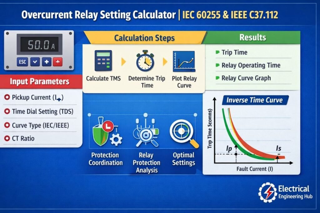
Table of Contents
Table of Contents
Overcurrent Relay Setting Calculator
Overcurrent Relay Setting Calculator
Calculate phase overcurrent (51) pickup, time multiplier, and instantaneous (50) settings for IDMT relays under IEC 60255 and IEEE C37.112 characteristics.
System & CT Data
Enter the CT ratio and the full load current of the protected feeder, motor, or transformer.
Relay Curve & Plug Setting
Select the IDMT characteristic and desired pickup (plug setting) as a percentage of CT primary rating.
Coordination Point
Enter the fault current expected at the relay location and the operating time required at that fault level, as set by your coordination study.
Instantaneous Element (50) Setting
The instantaneous element must stay above load inrush/starting current and above the maximum fault current at the far end of the next downstream zone, to preserve coordination.
Time-Current Characteristic
Plot of operating time against multiples of pickup current, using the curve and recommended time multiplier from the Pickup & TMS tab. The marked point is the operating time at your entered fault current.
Curve Family Reference
General guidance on where each characteristic is typically applied. Always confirm against the protection study and relay manufacturer’s manual.
Standard Inverse (SI)
The most common general-purpose curve for feeder and transformer overcurrent protection. Moderate inverse slope, good balance between fast fault clearance and load coordination.
Very Inverse (VI)
Steeper slope than SI, useful where fault current drops significantly with distance, such as long distribution feeders, giving better discrimination between relay stages.
Extremely Inverse (EI)
Very steep curve suited to protecting equipment with high inrush or starting currents, such as transformers and motors, since it stays slow near pickup but trips fast at high fault levels.
Long Time Inverse (LTI)
Shallow, slow-acting curve used for backup or ground fault schemes and applications needing extended time delay at moderate overcurrent.
Definite Time (DT)
Operating time is fixed regardless of fault magnitude. Used where simple, predictable coordination margins are preferred over an inverse characteristic.
IEEE Moderately / Very / Extremely Inverse
ANSI/IEEE equivalents to the IEC family, common on North American numerical relays, with a slightly different curve shape and time dial convention.
How to Use This Calculator
- Enter CT data. Input the CT primary rating and select the secondary (1 A or 5 A) used by your relay.
- Enter full load current. Use the actual or design full load current of the protected feeder, motor, or transformer.
- Choose the curve and plug setting. Select an IEC or IEEE characteristic and the pickup percentage from your coordination study.
- Enter the coordination point. Provide the fault current expected at the relay and the operating time you need at that fault level.
- Read the results. The tool returns the pickup current, plug setting multiplier, and the recommended time multiplier setting, rounded to a realistic relay step.
- Check the instantaneous tab. Enter downstream fault current and inrush data to get a coordinated instantaneous pickup recommendation.
- Review the curve. The Time-Current Curve tab plots the full characteristic so you can visually confirm the operating point.
What is an Overcurrent Relay?
An overcurrent relay is a protective device that detects excessive current flow in electrical systems and sends a trip signal to the circuit breaker when current exceeds the preset limit. It helps protect transformers, motors, generators, and feeders from damage caused by overloads and short circuits.
| Parameter | Description |
|---|---|
| Function | Detects abnormal current conditions |
| Protection Type | Overload and short-circuit protection |
| Common Settings | Pickup current, time delay, curve selection |
Understanding how an overcurrent relay works and its protection principles helps engineers select proper relay settings before performing calculations. Accurate relay coordination ensures reliable operation and minimizes unnecessary tripping in power systems.
What Is an Overcurrent Relay Setting Calculator?
An Overcurrent Relay Setting Calculator is an engineering tool used to calculate relay pickup current and operating time based on system parameters. It assists in configuring protective relays so they trip only when current exceeds predetermined limits.
The calculator is commonly used for:
- Industrial power distribution
- Commercial electrical installations
- Utility substations
- Generator protection
- Transformer protection
- Motor protection
- Feeder protection
By entering system values such as full-load current, CT ratio, fault current, relay curve, and TMS, users can quickly determine suitable relay settings.
Causes of Overcurrent in Power System
Overcurrent occurs when the current flowing through electrical equipment exceeds its rated capacity due to faults or abnormal operating conditions. Understanding the causes of overcurrent helps engineers select proper protection settings using an Overcurrent Relay Setting Calculator and avoid equipment damage.
| Cause | Description |
|---|---|
| Short Circuit Fault | Excessive current flow caused by phase-to-phase or phase-to-ground faults |
| Overloaded Equipment | Motors, transformers, or cables operating above their rated load |
| Motor Starting Current | High inrush current during large motor acceleration |
| Insulation Failure | Breakdown of insulation creating unintended current paths |
For detailed information about fault conditions and prevention methods, refer to our guide on common causes of overcurrent in power systems. Proper relay coordination ensures fast fault clearance while maintaining system reliability.
Why Correct Relay Settings Matter
Incorrect relay settings can create several problems in electrical systems. A relay set too low may trip during motor starting or temporary overloads. A relay set too high may fail to clear dangerous faults quickly.
Proper settings provide several advantages.
| Benefit | Description |
|---|---|
| Improved Safety | Clears faults before equipment damage occurs |
| Better Selectivity | Only the nearest protective device trips |
| Reduced Downtime | Prevents unnecessary outages |
| Equipment Protection | Protects cables, transformers, motors, and generators |
| Regulatory Compliance | Supports IEC and IEEE protection practices |
Inputs Required for Relay Setting Calculation
An Overcurrent Relay Setting Calculator requires several electrical parameters before calculating the recommended settings.
| Input Parameter | Purpose |
|---|---|
| Full Load Current (FLC) | Normal operating current |
| CT Ratio | Converts primary current to relay current |
| Maximum Fault Current | Determines relay operating time |
| Pickup Setting | Current level that initiates relay operation |
| Time Multiplier Setting (TMS) | Adjusts relay operating speed |
| Relay Characteristic Curve | Standard inverse, very inverse, or extremely inverse |
Accurate field measurements improve the reliability of calculated results.
Basic Formula Used
The relay pickup current depends on the selected percentage of rated current.
Pickup Current
Pickup Current = Full Load Current × Pickup Setting (%)
The Plug Setting Multiplier (PSM) is calculated as:
PSM = Fault Current ÷ Pickup Current
Relay operating time is then calculated using the selected IEC or IEEE inverse time equation together with the Time Multiplier Setting.
Modern numerical relays perform these calculations automatically, but understanding the formulas helps during commissioning and relay coordination studies.
Example of Relay Setting Calculation
Consider a feeder with the following data.
| Parameter | Value |
|---|---|
| Full Load Current | 180 A |
| CT Ratio | 200/5 |
| Pickup Setting | 125% |
| Maximum Fault Current | 2400 A |
| Relay Curve | Standard Inverse |
| TMS | 0.2 |
Step 1: Calculate Pickup Current
Pickup Current = 180 × 1.25
Pickup Current = 225 A
Step 2: Calculate PSM
PSM = 2400 ÷ 225
PSM = 10.67
Step 3: Determine Operating Time
Using the IEC Standard Inverse equation with TMS 0.2, the relay operating time is obtained from the relay characteristic curve or calculated automatically by the Overcurrent Relay Setting Calculator. For detailed manual calculation follow our guide on Overcurrent Protection Relay Settings, which explains in detail all the formulas involved.
Types of Overcurrent Relays
Understanding relay types helps you choose the correct inputs in an Overcurrent Relay Setting Calculator and apply the appropriate IEC 60255 or IEEE C37.112 settings. Different relay characteristics are selected based on the protected equipment, fault level, and required coordination with upstream and downstream devices. For a detailed comparison, read our guide on different overcurrent relay types and their applications.
| Relay Type | Typical Application |
|---|---|
| Instantaneous (50) | High fault current protection |
| Definite Time (51DT) | Feeders and distribution circuits |
| Inverse Time | General power system protection |
| Very Inverse | Long overhead feeders |
| Extremely Inverse | Transformer and motor protection |
GFCI vs. Overcurrent Protection: Different Safety Functions
Although both devices improve electrical safety, they protect against different hazards. An overcurrent relay setting tool helps engineers coordinate relays to detect overloads and short circuits, while a GFCI protects people from electric shock by sensing ground-fault current imbalance.
Understanding this difference prevents incorrect device selection in residential, commercial, and industrial systems.
| Feature | GFCI | Overcurrent Protection |
|---|---|---|
| Primary Purpose | Prevent electric shock | Protect cables and equipment |
| Detects | Ground faults | Overloads and short circuits |
| Typical Devices | GFCI breaker/receptacle | Relay, fuse, circuit breaker |
For a detailed comparison with applications and selection guidelines, read our guide on ground-fault protection vs. overcurrent protection. This article complements the Overcurrent Relay Setting Calculator by explaining where each protection method should be used.
Types of Overcurrent Relay Curves
Different applications require different inverse characteristics.
| Relay Curve | Typical Application |
|---|---|
| Standard Inverse | General feeder protection |
| Very Inverse | Distribution feeders with higher fault variations |
| Extremely Inverse | Transformer and cable protection |
| Long Time Inverse | Overload protection |
| Definite Time | Fixed operating delay applications |
Selecting the correct curve improves coordination with upstream and downstream protective devices.
Factors That Affect Relay Settings
Several electrical parameters influence relay performance.
CT Ratio
Incorrect CT selection results in inaccurate relay measurements. Always verify CT accuracy and burden before calculating settings.
Load Characteristics
Motors draw high inrush currents during starting. Relay pickup should remain above the starting current while still detecting faults quickly.
Fault Level
Higher fault current generally reduces relay operating time according to the selected inverse curve.
Coordination Study
Every relay should coordinate with adjacent protective devices to maintain system selectivity.
System Expansion
Future increases in connected load should be considered while selecting relay settings.
Typical Pickup Setting Guidelines
The following table provides general industry practices.
| Equipment | Typical Pickup Setting |
|---|---|
| Motor Feeders | 110–125% of FLC |
| Distribution Feeders | 125–150% of Load Current |
| Transformers | 125–150% of Rated Current |
| Generators | Based on manufacturer recommendations |
| Cables | According to cable ampacity and coordination study |
Actual settings should always be verified through a protection coordination study.
Overcurrent Protection of Transformer
Transformers require reliable protection against excessive current caused by short circuits, overloads, and system faults. Proper coordination between protective devices ensures fast fault clearance while avoiding unnecessary trips. A transformer protection scheme commonly includes overcurrent relays, circuit breakers, and backup protection functions.
| Protection Function | Purpose |
|---|---|
| Instantaneous Overcurrent | Clears severe short-circuit faults quickly |
| Time Overcurrent | Provides coordinated overload and fault protection |
| Earth Fault Protection | Detects ground fault currents |
For detailed information about relay coordination, pickup settings, and protection methods, explore our guide on transformer overcurrent protection to understand how transformer faults are detected and cleared effectively.
Overcurrent Relay Testing Procedure
After calculating relay parameters, the next step is verifying that the protection device operates correctly through an Overcurrent Relay Testing Procedure. Testing confirms pickup current, time delay, and trip characteristics according to IEC 60255 and IEEE C37.112 requirements.
| Test Parameter | Purpose |
|---|---|
| Pickup Current Test | Verifies relay operating threshold |
| Time Delay Test | Confirms inverse or definite time response |
| Trip Test | Checks breaker command operation |
A proper testing process helps identify incorrect settings, wiring issues, or relay performance problems before energizing the system. For a detailed step-by-step guide, refer to our complete guide on relay testing methods and field verification procedures.
Common Mistakes During Relay Setting
Avoid these common errors when configuring protective relays.
- Using incorrect CT ratios
- Ignoring motor starting current
- Selecting an unsuitable relay curve
- Using excessive TMS values
- Not coordinating with upstream breakers
- Ignoring minimum fault current levels
- Copying settings from another installation without verification
Reviewing relay calculations before commissioning helps prevent nuisance tripping and equipment damage.
IEC and IEEE Standards
Relay calculations are generally based on internationally recognized standards.
| Standard | Purpose |
|---|---|
| IEC 60255 | Measuring relays and protection equipment |
| IEC 60947 | Low-voltage switchgear coordination |
| IEEE C37 Series | Protective relay application and coordination |
| NEC Article 240 | Overcurrent protection requirements |
Following these standards improves protection system reliability and simplifies compliance during inspections.
Best Practices for Relay Coordination
Effective relay coordination requires more than selecting a pickup current.
- Verify transformer impedance values.
- Confirm available fault current.
- Check CT polarity and ratio.
- Select the appropriate inverse curve.
- Coordinate with upstream circuit breakers.
- Perform secondary injection testing.
- Validate settings after commissioning.
- Update settings whenever the electrical system changes.
These practices improve system protection and reduce unexpected outages.
Related Guides & Tools
- Overload Relay Setting Calculator
- Earth Fault Relay Setting Calculator
- Applications of Overcurrent Relays
- Differential Protection Relay Setting Calculator
Frequently Asked Questions
What is an Overcurrent Relay Setting Calculator used for?
It calculates pickup current, relay operating time, and coordination settings to protect electrical equipment from overloads and short circuits.
How is relay pickup current selected?
Pickup current is usually selected above the maximum normal load current while remaining sensitive enough to detect fault conditions.
Which relay curve should I choose?
Standard inverse is suitable for most feeder applications, while very inverse and extremely inverse curves are commonly used for transformers and cable protection.
Can one relay setting work for every installation?
No. Relay settings depend on load current, fault level, CT ratio, equipment type, and the results of the protection coordination study.
Conclusion
An Overcurrent Relay Setting Calculator is an essential engineering tool for designing safe and reliable electrical protection systems. It simplifies relay calculations, improves coordination between protective devices, and reduces the risk of unnecessary tripping or equipment damage.
By entering accurate system parameters and selecting the correct relay characteristics, engineers can achieve dependable protection for feeders, transformers, motors, and generators while complying with IEC and IEEE standards. When combined with proper testing and coordination studies, accurate relay settings contribute to safer electrical installations and improved system performance over the long term.
Follow Us on Social:
Subscribe our Newsletter on Electrical Insights for latest updates from Electrical Engineering Hub
#OvercurrentRelaySettingCalculator, #OvercurrentRelay, #RelayProtection, #PowerSystemProtection, #ElectricalEngineering, #ProtectionRelay, #IEC60255, #IEEEC37112, #PowerSystems, #ElectricalCalculators
Overcurrent Relay Setting Calculator | IEC 60255 & IEEE C37.112 : Electrical Engineering Hub

Overcurrent Relay Setting Calculator based on IEC 60255 and IEEE C37.112 standards. Calculate pickup current, time dial settings, relay coordination, and improve power system protection accuracy.
Price Currency: USD
Operating System: Web Browser
Application Category: UtilitiesApplication
