
Overcurrent Protection of Transformer: Working Principles, Methods and Relay Settings Guide
Quick Overview of Transformer Overcurrent Protection
| Parameter | Description |
|---|---|
| Main Purpose | Protect transformer windings from excessive current damage |
| Common Devices | Overcurrent relays, circuit breakers, fuses |
| Protection Types | Instantaneous, definite time, and inverse time protection |
| Main Standards | IEC 60255, IEEE C37.91, IEC 60076 |
Transformers are critical components in electrical networks, and their failure can lead to major power interruptions. Proper Overcurrent Protection of Transformer helps prevent damage caused by short circuits, overload conditions, and abnormal current flow. It detects excessive current levels and disconnects the transformer from the power system before severe thermal and mechanical damage occurs.
Transformer protection systems are designed by considering transformer rating, fault current level, coordination requirements, and network operating conditions. A properly configured protection scheme improves system reliability and reduces equipment downtime.
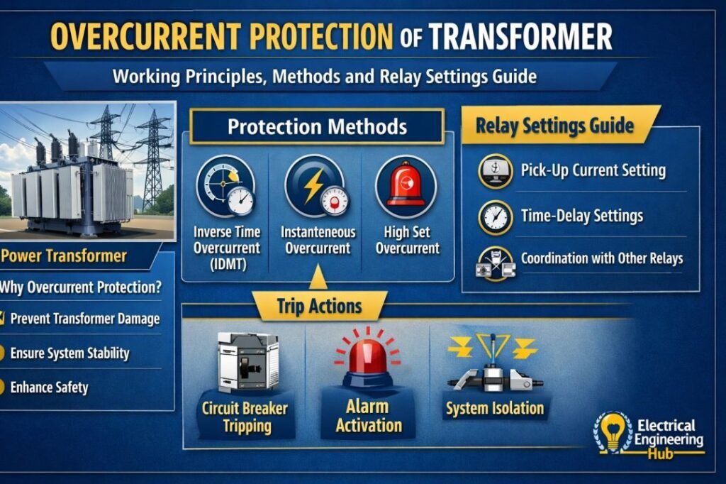
Why Overcurrent Protection of Transformer Is Required
Transformers experience different types of electrical faults during operation, including phase-to-phase faults, earth faults, and internal winding faults. These faults create high current conditions that can rapidly increase winding temperature and damage insulation.
The main purpose of Overcurrent Protection of Transformer is to identify abnormal current conditions and initiate a trip command to the circuit breaker. This prevents excessive stress on transformer windings, bushings, and connected equipment.
Common causes that require transformer overcurrent protection include:
- Short circuit faults on primary or secondary sides
- Cable faults connected to transformer terminals
- Excessive load demand
- Insulation breakdown inside transformer windings
- Ground faults in distribution systems
- Incorrect load balancing between phases
Types of Transformer Overcurrent Protection
Different protection methods are used depending on transformer size, voltage level, and application. Small distribution transformers may use simple fuse protection, while large power transformers require advanced relay-based protection.
| Protection Method | Application | Advantages |
|---|---|---|
| Fuse Protection | Small distribution transformers | Simple and economical |
| Instantaneous Overcurrent Relay | High fault current conditions | Fast fault clearance |
| Time Overcurrent Relay | Distribution and industrial systems | Better coordination |
| Earth Fault Relay | Ground fault protection | Improves safety |
| Differential Protection | Large power transformers | High accuracy |
How Transformer Overcurrent Relay Works
An overcurrent relay continuously monitors the current flowing through the transformer. Current transformers (CTs) reduce the actual line current to a measurable value that can be processed by the relay.
When current exceeds the preset pickup value, the relay starts timing according to its operating curve. If the fault remains longer than the allowed duration, the relay sends a trip signal to the circuit breaker.
Relay operation mainly depends on:
- Pickup current setting
- Time multiplier setting
- Relay characteristic curve
- Fault current magnitude
- Coordination with upstream and downstream protection devices
For accurate relay coordination, engineers often use a dedicated transformer relay setting calculation tool to determine suitable protection parameters based on system requirements.
Overcurrent Relay Settings for Transformer Protection
Correct relay settings are essential because incorrect values can cause unwanted trips or delayed fault clearance. The protection engineer must balance sensitivity and selectivity.
The main relay settings include:
| Setting Parameter | Function |
|---|---|
| Pickup Current | Defines the minimum fault current required for relay operation |
| Time Dial Setting | Adjusts relay operating time |
| Instantaneous Setting | Provides rapid response for severe faults |
| CT Ratio | Converts primary current into relay input current |
The relay pickup value is normally selected above the transformer full-load current but below the minimum expected fault current. This ensures normal operating conditions do not cause unnecessary tripping.
Engineers can simplify this process using an IEC and IEEE based overcurrent relay setting guide to verify time-current characteristics and coordination margins.
Transformer Protection Coordination
Protection coordination ensures that the nearest protective device operates first during a fault. This prevents unnecessary shutdown of larger sections of the electrical network.
A coordinated protection system considers:
- Transformer short circuit impedance
- Downstream feeder protection
- Breaker operating time
- Relay curve selection
- Fault clearing requirements
| Equipment Location | Preferred Protection Action |
|---|---|
| Transformer secondary feeder | Feeder relay operates first |
| Transformer primary side | Transformer relay provides backup |
| Upstream substation | Backup protection operates after delay |
Proper coordination between transformer relays and feeder protection improves power system stability. A detailed review of overcurrent relay coordination calculations can help engineers achieve correct discrimination between protection devices.
Factors Affecting Transformer Overcurrent Protection Settings
Several electrical and operational factors influence protection settings. A fixed setting cannot be applied to every transformer because each installation has different fault levels and operating conditions.
Important factors include:
Transformer Rating
The transformer kVA or MVA rating determines the normal operating current. Larger transformers generally require more advanced protection systems.
Transformer Impedance
Transformer impedance affects the available short circuit current. Lower impedance transformers allow higher fault currents, requiring faster protection response.
System Voltage Level
Higher voltage transformers usually need more precise relay coordination because faults can impact a larger electrical network.
Load Characteristics
Industrial loads with motors and large starting currents require careful settings to avoid unnecessary relay operation.
Common Mistakes in Transformer Overcurrent Protection
Incorrect protection design can reduce system reliability and increase equipment damage risk. Common mistakes include:
- Setting relay pickup current too low
- Ignoring transformer inrush current
- Poor coordination with feeder protection
- Using incorrect CT ratios
- Selecting unsuitable relay curves
Transformer inrush current is especially important because it can be several times higher than normal current during energization. Protection settings must distinguish between temporary magnetizing current and actual faults.
Benefits of Proper Transformer Protection
A correctly designed protection system provides several operational advantages:
- Prevents transformer winding damage
- Reduces repair and replacement costs
- Improves electrical system reliability
- Minimizes production downtime
- Enhances personnel safety
- Supports better fault analysis
Related Guides & Tools
- Overcurrent Relay Setting Calculator
- Difference Between GFCI and Overcurrent Protection
- Types of Overcurrent Relays
- Causes of Overcurrent in Power System
Conclusion
Overcurrent Protection of Transformer is an essential part of modern power system safety and reliability. It protects transformers from damaging fault currents while maintaining continuity of electrical supply. Selecting suitable relay settings, CT ratios, and coordination methods ensures that protection devices operate accurately when faults occur.
A well-designed transformer protection scheme combines proper engineering calculations, reliable relays, and correct coordination practices. Regular testing and maintenance further improve protection performance throughout the transformer service life.
Follow Us on Social:
Subscribe our Newsletter on Electrical Insights for latest updates from Electrical Engineering Hub
OvercurrentProtection, #TransformerProtection, #PowerSystemProtection, #TransformerRelay, #ElectricalEngineering, #PowerEngineering, #ProtectionRelay, #ElectricalSafety, #TransformerFaults, #SubstationProtection
