
Difference Between Winding Resistance and Insulation Resistance
The difference between winding resistance and insulation resistance is important when testing electric motors, generators, transformers, and other electrical equipment. Winding resistance checks the condition of the copper or aluminum conductors, while insulation resistance checks the quality of insulation between conductors and earth.
From my hands-on experience troubleshooting motors and electrical equipment, winding resistance measurements help identify phase imbalance and winding defects, while insulation resistance tests assess insulation integrity and leakage risks. Understanding this distinction is essential for accurate motor diagnostics and safe maintenance.
Both tests help detect faults before equipment fails. However, they use different instruments, test methods, and measurement units. Understanding these differences helps electricians and maintenance engineers diagnose motor faults and plan preventive maintenance.
Difference Between Winding Resistance and Insulation Resistance
| Parameter | Winding Resistance | Insulation Resistance |
|---|---|---|
| Purpose | Checks winding continuity and electrical resistance | Checks insulation condition |
| Main faults detected | Open windings, loose joints, poor connections, phase imbalance | Moisture, contamination, insulation damage |
| Test instrument | Digital low-resistance ohmmeter or micro-ohmmeter | Insulation resistance tester (megohmmeter) |
| Measurement unit | Ohms (Ω) or milliohms (mΩ) | Megohms (MΩ) or gigohms (GΩ) |
| Test voltage | Low DC test current or voltage | Higher DC test voltage |
| Test connections | Across winding terminals | Between winding and earth, or between isolated windings |
| Typical result | Low, stable resistance within expected limits | Sufficiently high resistance for the equipment |
| Common application | Motor winding comparison and connection checks | Motor insulation and earth leakage risk assessment |
| Main concern | Conductor and connection condition | Electrical insulation integrity |
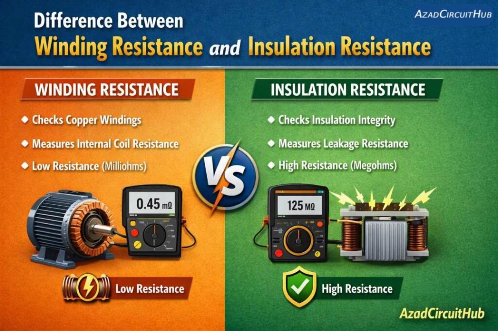
Table of Contents
Table of Contents
What Is Winding Resistance?
Winding resistance is the electrical resistance of a motor or transformer winding. It mainly depends on the conductor material, wire length, cross-sectional area, and temperature.
A winding with excessive resistance may have a poor connection, damaged conductor, incorrect repair, or loose terminal joint. An open winding may show an abnormally high resistance or no continuity.
For a three-phase motor, technicians commonly measure resistance between U-V, V-W, and W-U terminals. The readings should be close to one another when the windings have the same design and are tested under comparable conditions.
For example, a motor may produce the following readings:
| Phase Pair | Measured Resistance |
|---|---|
| U-V | 1.20 Ω |
| V-W | 1.22 Ω |
| W-U | 1.21 Ω |
These readings are closely matched. However, the acceptable range depends on motor design, winding temperature, test accuracy, and manufacturer specifications.
For more reference values, see the 3 phase motor winding resistance values guide.
What Is Insulation Resistance?
Insulation resistance measures how well electrical insulation prevents current from flowing between conductors or from a conductor to earth.
Motor windings use insulation to separate turns, phases, and conductive motor parts. Damaged or contaminated insulation can allow leakage current, increasing the risk of electric shock, earth faults, and winding failure.
An insulation resistance tester applies a specified DC test voltage and measures the resulting leakage current. The instrument then calculates the resistance, commonly displaying the result in megohms.
For example, a motor winding may measure 200 MΩ between a winding and the motor frame. Whether this result is acceptable depends on the motor rating, temperature, insulation system, test voltage, and applicable standard.
Insulation resistance can decrease because of:
- Moisture inside the motor
- Dust, oil, or conductive contamination
- Cracked or aged insulation
- Overheating
- Long periods of storage in humid conditions
- Mechanical damage to winding insulation
Always isolate the motor from its power supply and disconnect sensitive electronic equipment before insulation testing. Follow the manufacturer’s instructions for the correct test voltage and discharge the winding safely after testing.
How to Test Winding Resistance and Insulation Resistance
Although both tests assess motor condition, the procedures are different.
Winding Resistance Test
- Isolate the motor from the power supply and apply lockout/tagout procedures.
- Verify that the motor is de-energized.
- Identify the winding terminals and isolate external circuits where necessary.
- Use a suitable low-resistance meter to measure each phase pair.
- Record the readings and compare them with the manufacturer’s data or previous test results.
- Account for winding temperature when comparing measurements.
For low-resistance windings, a four-wire measurement can reduce errors caused by test-lead resistance.
Insulation Resistance Test
- Isolate the motor and verify that it is de-energized.
- Disconnect the motor from variable-frequency drives, electronic controls, and other equipment that could be damaged by the test voltage.
- Connect the insulation tester between the selected winding and earth, or between isolated windings as required.
- Apply the manufacturer’s specified DC test voltage for the required duration.
- Record the resistance and test conditions.
- Allow the winding to discharge safely before touching the terminals or reconnecting equipment.
Do not apply a generic test voltage to every motor. Use the applicable standard and manufacturer guidance.
Comparison of Common Motor Test Results
| Test Result | Possible Meaning | Recommended Action |
|---|---|---|
| One phase pair has higher resistance | Loose joint, poor connection, or winding damage | Inspect connections and repeat the test |
| One phase pair has much lower resistance | Possible shorted turns or measurement error | Verify the test setup and arrange further diagnostics |
| All winding readings are open | Disconnected leads or an open winding | Check terminals and winding continuity |
| Low insulation resistance to earth | Moisture, dirt, or insulation deterioration | Inspect, clean or dry as appropriate, then retest |
| Insulation resistance falls over time | Possible moisture ingress or insulation aging | Compare trends and investigate the cause |
| Both tests show abnormal results | Multiple faults may be present | Perform a detailed motor condition assessment |
A winding resistance test cannot confirm that insulation is healthy. Likewise, a high insulation resistance reading does not prove that winding resistance is balanced or that the motor has no shorted turns.
How to Interpret Winding Resistance Imbalance
For three-phase motors, winding resistance imbalance can help identify differences between phase measurements. A common calculation is:
Resistance imbalance (%) = (Maximum deviation from the average resistance ÷ Average resistance) × 100
For example, if the average resistance is 1.20 Ω and the maximum deviation is 0.02 Ω, the imbalance is approximately 1.67%.
The acceptable limit depends on the motor, measurement method, and applicable guidance. Temperature differences and poor test connections can also affect the result.
Refer to Acceptable Motor Winding Resistance Imbalance for the calculation method and troubleshooting guidance. You can also use the 3 Phase Motor Winding Resistance Chart by HP to compare typical resistance ranges for different motor sizes.
Frequently Asked Questions
1. Can winding resistance be measured with a megger?
A megger is designed mainly for insulation resistance testing. Use a suitable low-resistance ohmmeter or micro-ohmmeter for accurate winding resistance measurements, especially when the winding resistance is very low.
2. What is a good insulation resistance value for a motor?
There is no single value suitable for every motor. The required minimum depends on the motor rating, insulation system, temperature, and applicable standard. Compare readings with manufacturer recommendations and previous test results.
3. Does high winding resistance mean motor insulation is damaged?
Not necessarily. High winding resistance may indicate a loose connection, damaged conductor, or incorrect measurement. Insulation damage must be assessed separately using suitable insulation tests.
4. Can a motor pass an insulation resistance test but still be faulty?
Yes. A motor can show high insulation resistance and still have winding imbalance, shorted turns, poor connections, bearing problems, or mechanical damage. Additional tests may be needed.
5. How often should motor winding and insulation resistance be tested?
Test intervals depend on operating conditions, criticality, manufacturer guidance, and the maintenance program. Motors exposed to moisture, dust, heat, or frequent starts may need more frequent checks.
Conclusion
The main difference between winding resistance and insulation resistance is what each test measures. Winding resistance evaluates the electrical resistance and balance of the conductors, while insulation resistance assesses the insulation between windings and earth or other isolated conductors.
Both tests are useful for preventive maintenance, but neither replaces the other. Record readings, compare results with reliable reference data, and investigate changes before returning a suspect motor to service.
Get new guides in your feed. Follow Electrical Insights on LinkedIn for new electrical standards guides, calculators and design tips from Azad Circuit Hub.
#WindingResistance, #InsulationResistance, #MotorTesting, #ElectricalTesting, #MotorWinding, #MeggerTest, #WindingResistanceTest, #InsulationResistanceTest, #ElectricalEngineering, #MotorTroubleshooting
