
Acceptable Motor Winding Resistance Imbalance: Tolerance, Causes & Troubleshooting
The acceptable motor winding resistance imbalance depends on the motor design, winding condition, temperature, and test method. A three-phase motor should have closely matched winding resistance readings when measured correctly. A large difference may indicate a loose connection, damaged winding, corrosion, or another electrical fault.
For routine troubleshooting, a resistance imbalance below 3% is often treated as a useful screening target, while readings above 5% deserve investigation. These are practical guidelines, not universal acceptance limits. Always follow the motor manufacturer’s specifications and applicable maintenance procedures.
Acceptable Motor Winding Resistance Imbalance
| Resistance imbalance | Practical assessment | Recommended action |
|---|---|---|
| Below 3% | Generally well balanced | Record the readings |
| 3–5% | Possible variation | Repeat the test and monitor |
| Above 5% | Significant difference | Investigate connections and windings |
| Above 10% | Potential serious fault | Stop and diagnose before operation |
These thresholds are preliminary screening guidelines for comparable phase resistance readings. Small motors, low-resistance windings, and different winding configurations may require more careful measurement.
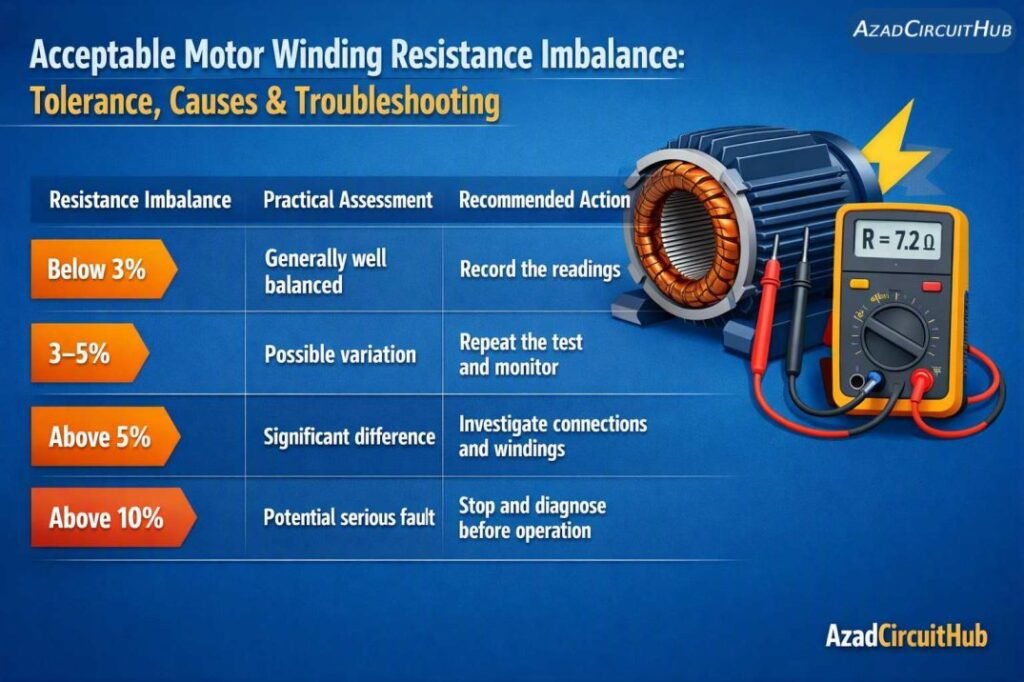
Table of Contents
Table of Contents
What Is an Acceptable Motor Winding Resistance Imbalance?
An acceptable motor winding resistance imbalance is the difference between the measured phase winding resistances, expressed as a percentage. In a healthy three-phase motor, the readings should be reasonably close under the same test conditions.
For example, if a motor measures 2.01 Ω, 2.00 Ω, and 1.99 Ω, the readings are closely matched. However, readings of 2.00 Ω, 2.00 Ω, and 2.40 Ω indicate a much larger difference that needs investigation.
The acceptable difference between three phase motor winding resistance readings depends on the manufacturer’s tolerance. Copper temperature, lead resistance, terminal condition, and meter accuracy can affect the results.
For reference values across different motor ratings and voltages, consult the 3 phase motor winding resistance values guide.
How to Calculate Motor Winding Resistance Imbalance
Use the following formula to calculate resistance imbalance from three phase readings.
Step 1: Measure all three phase resistances.
Record the resistance values as R, Y, and B. For a motor with accessible winding terminals, measure each winding separately when the circuit configuration permits.
Step 2: Calculate the average resistance.
Average resistance = (R + Y + B) / 3
Step 3: Find the highest deviation from the average.
Maximum deviation = Highest absolute difference between any phase reading and the average.
Step 4: Calculate the percentage imbalance.
Resistance imbalance (%) = (Maximum deviation / Average resistance) × 100
Worked example
Suppose a motor has these measured resistances:
| Phase | Measured resistance |
|---|---|
| R | 10.0 Ω |
| Y | 10.2 Ω |
| B | 9.8 Ω |
Average resistance = (10.0 + 10.2 + 9.8) / 3 = 10.0 Ω
Maximum deviation = 0.2 Ω
Resistance imbalance = (0.2 / 10.0) × 100 = 2%
The readings are closely balanced under this screening method. Confirm the result against the motor manufacturer’s specifications.
How to Calculate 5% Tolerance of a Three-Phase Motor
To calculate a 5% resistance tolerance, multiply the average resistance by 0.05.
5% tolerance = Average resistance × 0.05
For example, if the average resistance is 20 Ω:
5% tolerance = 20 × 0.05 = 1 Ω
The corresponding screening range is 19–21 Ω around the average. However, the maximum-deviation formula above is the method used to calculate the actual percentage imbalance.
A common mistake is to compare the highest and lowest readings directly and divide their difference by the average. This produces a different percentage. Use a consistent formula when comparing test results.
Motor Winding Resistance Imbalance Causes and Effects
Unbalanced winding resistances can develop because of connection problems, insulation damage, or defects within the winding. Some causes are external to the motor itself.
| Cause | Typical indication | Recommended fix |
|---|---|---|
| Loose terminals | Unstable readings or heating at a connection | Isolate power and inspect and tighten to the specified torque |
| Corrosion or oxidation | Increased resistance at terminals | Clean or replace affected connections using approved procedures |
| Moisture ingress | Unusual readings alongside low insulation resistance | Dry the motor using an approved method and investigate the source of moisture |
| Shorted winding turns | Abnormal resistance or current, sometimes with overheating | Perform further winding tests and repair or rewind as needed |
| Damaged winding lead | One phase shows an unusually high or open reading | Inspect and repair the lead or connection |
| Incorrect measurement setup | Readings change with probe placement or lead resistance | Clean contact points and repeat with a suitable low-resistance meter |
The effects of winding resistance imbalance can include unequal phase currents, extra heating, reduced efficiency, nuisance trips, and shortened insulation life. However, resistance imbalance alone does not prove that a winding is defective. Further tests may be needed.
Three-Phase Motor Resistance Readings: Worked Examples
The following examples illustrate common troubleshooting questions. The readings are illustrative diagnostic examples, not verified field measurements.
Example 1: R = 14, Y = 34.6, B = 34.7 ohms — is this OK?
No. If these are directly comparable winding resistance readings, the difference is too large to dismiss as normal variation.
Average = (14 + 34.6 + 34.7) / 3 = 27.77 Ω
Maximum deviation = 34.7 − 27.77 = 6.93 Ω
Imbalance = (6.93 / 27.77) × 100 = approximately 25%
This is a significant discrepancy. First confirm the meter range, probe contact, terminal configuration, and measurement points. If the readings are valid, investigate the low-resistance phase and its connections before returning the motor to service.
Example 2: R = 10.1, Y = 10.3, B = 10.2 ohms
Average = 10.2 Ω
Maximum deviation = 0.1 Ω
Imbalance = (0.1 / 10.2) × 100 = approximately 0.98%
These readings are closely balanced. Record the values and compare them with the manufacturer’s specifications and previous maintenance records.
Example 3: R = 4.8, Y = 5.0, B = 5.4 ohms
Average = 5.07 Ω
Maximum deviation = 0.33 Ω
Imbalance = (0.33 / 5.07) × 100 = approximately 6.6%
This result deserves investigation. Repeat the measurements after checking terminal tightness, contact quality, and temperature. If the imbalance remains, carry out additional winding diagnostics.
Acceptable Tolerance of Motor Winding Balance
There is no single percentage that applies to every motor. The appropriate limit depends on the manufacturer’s guidance, the winding resistance, and the precision of the measurement equipment.
For a motor with very low resistance, ordinary multimeter lead resistance can distort the result. A four-wire Kelvin resistance meter is often more suitable for accurate low-resistance measurements.
Use the following approach when assessing winding balance:
- Compare readings taken at similar winding temperatures.
- Disconnect the motor from the supply and isolate it before testing.
- Follow the manufacturer’s instructions for star or delta connections.
- Remove or account for external circuit paths where required.
- Repeat suspicious readings before concluding that a winding is damaged.
- Compare with previous test results whenever available.
The motor winding resistance chart provides additional reference information for checking expected resistance values across motor horsepower ratings and supply voltages. For Winding Resistance Chart by HP follow this detailed guide on 3 Phase Motor Winding Resistance Chart by HP.
Imbalance in Winding Resistance in a Three-Phase Traction Motor
Traction motors used in electric vehicles and rail applications may have different winding arrangements and inverter-driven operating conditions. Their resistance values should be evaluated according to the manufacturer’s test procedure rather than a generic industrial motor chart.
A traction motor can show misleading resistance readings if the inverter, temperature sensors, internal connections, or parallel winding paths remain connected during testing.
For these motors, isolate the power electronics as specified, verify the terminal configuration, and use approved diagnostic equipment. Do not apply a generic 5% acceptance limit unless the manufacturer supports it.
Motor Winding Resistance Unbalance vs Current Unbalance
Resistance imbalance and current imbalance are related but different measurements.
| Feature | Resistance imbalance | Current imbalance |
|---|---|---|
| Measurement | Winding resistance in ohms | Phase current in amperes |
| Test condition | Motor isolated from supply | Motor operating under load |
| Common causes | Loose joints, damaged windings, measurement errors | Voltage imbalance, load variation, winding faults |
| Main use | Checks winding and connection consistency | Checks operating electrical performance |
A motor can have balanced DC resistance readings and still draw unbalanced current because of unequal supply voltages, rotor problems, load conditions, or insulation faults. Likewise, a resistance discrepancy may not produce the same percentage of current imbalance.
For a complete diagnosis, combine resistance measurements with supply voltage checks, current measurements, insulation resistance testing, and other appropriate motor tests.
Step-by-Step Troubleshooting Procedure
- Switch off and isolate the motor supply using the site’s lockout/tagout procedure.
- Verify the absence of voltage before touching conductors.
- Identify the motor terminal arrangement and disconnect external paths where required.
- Measure all three phase winding resistances using consistent test points.
- Calculate the average and percentage imbalance.
- Inspect terminals, links, winding leads, and signs of moisture or corrosion.
- Repeat the measurements after correcting any connection or test setup problems.
- If the imbalance persists, arrange appropriate winding diagnostics or specialist repair.
Never measure winding resistance on an energized motor. Insulation resistance testing also requires suitable isolation and protection of sensitive electronic components.
Frequently Asked Questions
1. What is an acceptable motor winding resistance imbalance?
A value below 3% is a useful preliminary screening target for many comparable three-phase winding measurements. A result above 5% warrants investigation, but the manufacturer’s tolerance takes priority.
2. What is the acceptable difference between three-phase motor winding resistances?
The acceptable difference depends on the motor design, winding temperature, resistance level, and measurement accuracy. Compare all three readings using a consistent calculation method and the manufacturer’s specifications.
3. Can a motor run with 5% winding resistance imbalance?
It should not be assumed safe based on that number alone. Verify the readings and identify the cause before deciding whether operation is acceptable. Current imbalance, heating, and protection settings also matter.
4. Does winding resistance imbalance always mean a bad motor?
No. Loose terminals, corrosion, poor probe contact, and meter lead resistance can create misleading results. If the difference remains after correcting these issues, further winding tests may be needed.
5. What causes motor winding resistance to become unbalanced?
Common causes include loose or corroded terminals, damaged winding leads, shorted turns, moisture-related deterioration, and inconsistent test conditions. Correct the measurement setup first, then investigate the motor if the imbalance persists.
Final Recommendations
The best way to assess winding health is to establish a reliable baseline, measure all phases under consistent conditions, and compare the results with the motor manufacturer’s limits. Use the percentage imbalance as a screening tool, not as the only pass-or-fail criterion.
A small resistance difference may be normal, but a persistent discrepancy, unexplained current imbalance, or unusual heating should be investigated before continued operation. Accurate measurements and systematic troubleshooting help prevent unnecessary rewinding while reducing the risk of motor failure.
Follow Us on Social:
Subscribe our Newsletter on Electrical Insights for latest updates from Azad Circuit Hub
#MotorWindingResistance, #MotorResistanceImbalance, #ElectricMotorTesting, #MotorTroubleshooting, #WindingResistance, #MotorMaintenance, #ThreePhaseMotor, #ElectricalEngineering, #MotorFaultDiagnosis, #IndustrialMaintenance
