
3 Phase Motor Winding Resistance Chart by HP (1HP–250HP) – US Voltage Standards
A 3 phase motor winding resistance chart by HP helps electricians and maintenance technicians estimate the resistance they may measure across motor windings during troubleshooting. The reading depends on motor horsepower, rated voltage, winding design, connection type, temperature, and manufacturer specifications.
In the United States, common three-phase motor voltages include 208V, 230V, 460V, and 575V. Some industrial motors also operate at 600V. A motor’s horsepower alone cannot determine its exact winding resistance. Two motors with the same HP rating may show different ohm readings.
The tables below provide preliminary resistance ranges for field reference. They are illustrative estimates, not manufacturer specifications or pass/fail limits. Always compare actual measurements with the motor nameplate, factory data, and previous test records.
As an electrical engineer with 15+ years of field experience in industrial panels, motor control, and troubleshooting, I recommend comparing all three phase resistance readings with manufacturer specifications. Always account for winding temperature and test-lead resistance, especially on large motors. A balanced resistance reading alone does not rule out shorted turns or insulation failure.
3 Phase Motor Winding Resistance Chart by HP
The following table provides indicative line-to-line resistance ranges for common industrial motors operating at approximately 460–480V. The estimates assume conventional low-voltage induction motors and balanced three-phase windings.
| Motor HP | Rated Voltage | Typical Line-to-Line Resistance (Approx.) |
|---|---|---|
| 1 HP | 460–480V | 4–15 Ω |
| 2 HP | 460–480V | 2–8 Ω |
| 3 HP | 460–480V | 1.5–6 Ω |
| 5 HP | 460–480V | 0.8–3.5 Ω |
| 7.5 HP | 460–480V | 0.5–2.5 Ω |
| 10 HP | 460–480V | 0.3–1.8 Ω |
| 15 HP | 460–480V | 0.2–1.2 Ω |
| 20 HP | 460–480V | 0.15–0.9 Ω |
| 25 HP | 460–480V | 0.12–0.7 Ω |
| 30 HP | 460–480V | 0.10–0.6 Ω |
| 40 HP | 460–480V | 0.08–0.45 Ω |
| 50 HP | 460–480V | 0.06–0.35 Ω |
| 60 HP | 460–480V | 0.05–0.30 Ω |
| 75 HP | 460–480V | 0.04–0.25 Ω |
| 100 HP | 460–480V | 0.03–0.20 Ω |
| 125 HP | 460–480V | 0.025–0.16 Ω |
| 150 HP | 460–480V | 0.02–0.13 Ω |
| 200 HP | 460–480V | 0.015–0.10 Ω |
| 250 HP | 460–480V | 0.01–0.08 Ω |
Important: These ranges are broad, illustrative screening values, not verified industry-standard resistance ranges. Actual readings can fall outside them. Do not reject a motor or declare its windings healthy based on this table alone. Large-motor winding resistance often requires a low-resistance ohmmeter or a four-wire Kelvin measurement.
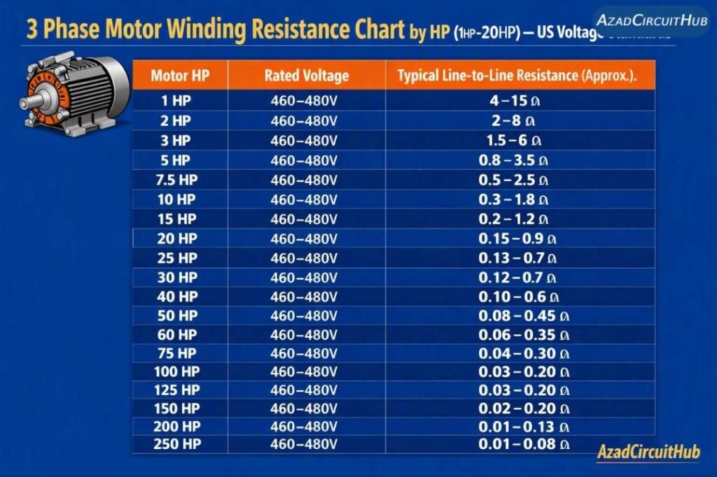
Table of Contents
Table of Contents
How Motor Voltage Affects Winding Resistance
Voltage rating affects the winding design, but resistance does not increase or decrease in a fixed proportion to voltage. The number of turns, wire size, winding configuration, and rated current all affect the measured resistance.
| Motor Voltage | Common US Application | Resistance Measurement Consideration |
|---|---|---|
| 208V | Commercial buildings | Check the nameplate voltage and connection diagram |
| 230V | Industrial and commercial equipment | Compare readings with the manufacturer’s specifications |
| 460V | Industrial motors | Common rating for motors connected to nominal 480V systems |
| 480V | Industrial power systems | Confirm whether the motor nameplate specifies 460V or another rating |
| 575V | Canadian and some North American industrial systems | Use the exact motor data for comparison |
| 600V | Industrial equipment | Confirm the actual nameplate rating and winding arrangement |
A 208V motor does not automatically have lower winding resistance than a 480V motor of the same horsepower. The resistance depends on the winding configuration and construction. For example, a motor connected in star can produce a different terminal-to-terminal reading from the same winding set connected in delta.
For a complete reference, see the 3 phase motor winding resistance values guide, which can help you understand resistance readings alongside motor voltage and connection type.
Why US Motor Nameplates Use HP and Volts Instead of kW
In the United States, three-phase motors commonly use horsepower (HP) to specify mechanical output and volts (V) to identify the rated supply voltage. This reflects established North American industrial practice. Kilowatts may also appear on motor nameplates and technical datasheets, particularly for international equipment.
Horsepower does not determine winding resistance by itself. The motor’s winding design, rated voltage, connection type, conductor size, and temperature all affect the measured ohm value. Always use manufacturer data when checking winding resistance.
Download the Motor Winding Resistance Reference PDF
Use our 3-phase motor winding resistance reference table (PDF) for a structured reference covering common motor horsepower ratings from 1/8 HP to 250 HP and US voltage classes of 208V, 230V, 460V, and 480V.
The guide explains how to measure phase-to-phase resistance, compare readings, calculate resistance imbalance, and identify when further testing is needed. Always confirm acceptable readings against the motor manufacturer’s specifications. Read full guide on Acceptable Motor Winding Resistance Imbalance and Tolerance here.
1 HP Three-Phase Motor Resistance
A 1 HP three-phase motor may operate at 208V, 230V, 460V, or another rated voltage. Its winding resistance varies with the winding design and whether the measurement is taken at the motor terminals or directly across an isolated winding.
| Motor Rating | Example Resistance Range | What to Check |
|---|---|---|
| 1 HP, 208V | Design-dependent | Verify the manufacturer’s resistance data |
| 1 HP, 230V | Design-dependent | Measure all three line-to-line combinations |
| 1 HP, 460V | Approximately 4–15 Ω as an illustrative screening range | Compare the readings and check winding balance |
Small motors can have relatively high winding resistance because they use finer wire and draw less current than larger motors. A reading that appears reasonable on a general chart may still be abnormal for a particular motor.
5 HP Motor Resistance at 600V
A 5 HP motor rated for a 600V system needs to be checked against its actual nameplate and winding specifications. Do not apply the 460–480V estimate directly to a 600V motor.
A higher voltage rating may involve more winding turns and different wire sizes. However, the actual resistance depends on the design, not voltage alone.
During testing:
- Disconnect the motor from its power source.
- Isolate it from the variable frequency drive, starter, and other connected equipment.
- Confirm that the circuit is de-energized and follow the site’s lockout/tagout procedure.
- Measure each phase combination using a suitable meter.
- Record the winding temperature and compare the results with manufacturer data.
10 HP, 2900 RPM Motor Winding Resistance
A 10 HP, approximately 2900 RPM motor is generally a two-pole motor operating near 3000 RPM at 50 Hz or 3600 RPM at 60 Hz, with actual speed reduced by slip under load. A 2900 RPM rating is common in 50 Hz applications.
Its resistance cannot be determined from horsepower and RPM alone. The voltage rating, frequency, winding arrangement, and manufacturer design are also required.
For a 10 HP, 460–480V motor, the illustrative range in the main chart is 0.3–1.8 Ω line to line. Treat this only as a preliminary reference, not an acceptable resistance specification for every motor.
15 HP Motor Resistance at 480V
A 15 HP, 480V motor may have a nameplate rating of 460V for use on a nominal 480V supply. Always check the motor’s permitted voltage range and connection diagram.
| Test | What the Result Can Indicate |
|---|---|
| U–V resistance | Resistance of one terminal pair |
| V–W resistance | Resistance of the second terminal pair |
| W–U resistance | Resistance of the third terminal pair |
| Phase-to-frame resistance | Insulation condition, when tested with an appropriate insulation tester |
The illustrative 460–480V line-to-line range for a 15 HP motor is 0.2–1.2 Ω. The actual value must come from the motor’s technical documentation or a reliable baseline measurement.
20 HP, 25 HP, and 30 HP Motor Resistance
These ratings are common in pumps, fans, compressors, conveyors, and industrial process equipment. Their winding resistance is often low enough that test-lead resistance can affect an ordinary multimeter reading.
| Motor Rating | Illustrative 460–480V Line-to-Line Range |
|---|---|
| 20 HP | 0.15–0.9 Ω |
| 25 HP | 0.12–0.7 Ω |
| 30 HP | 0.10–0.6 Ω |
For a 25 HP, 208V three-phase motor, do not assume the resistance will fall within the 25 HP, 460–480V range. A different voltage and winding design can produce a different result. Use the manufacturer’s specifications.
For a 30 HP motor, measure all three phase combinations and check whether the readings are consistent. A significant difference may indicate a loose terminal, damaged conductor, poor connection, or winding fault.
50 HP Motor Resistance at 480V and 208V
A 50 HP motor can be built for different voltage ratings. A motor designed for 480V service should not be treated as interchangeable with a 208V motor simply because both have the same horsepower.
| Motor Rating | Resistance Guidance |
|---|---|
| 50 HP, 480V | Illustrative range: 0.06–0.35 Ω line to line |
| 50 HP, 460V | Check the motor’s rated voltage and factory data |
| 50 HP, 208V | Use manufacturer-specific winding resistance data |
The phrase “50 HP 480/208 motor resistance” can refer to different motor configurations or equipment supplied at different voltages. Confirm the nameplate before interpreting a reading. A dual-voltage motor also may have different terminal connections for each rated voltage.
60 HP Motor Ohms and 200 HP Motor Ohm Reading
Large motors require more care because their winding resistance can be very low. Standard multimeters may not provide enough resolution to identify small resistance differences accurately.
| Motor Rating | Illustrative 460–480V Range | Recommended Approach |
|---|---|---|
| 60 HP | 0.05–0.30 Ω | Use a suitable low-resistance meter |
| 100 HP | 0.03–0.20 Ω | Check phase balance and historical results |
| 150 HP | 0.02–0.13 Ω | Consider a four-wire resistance test |
| 200 HP | 0.015–0.10 Ω | Follow manufacturer test procedures |
| 250 HP | 0.01–0.08 Ω | Use calibrated equipment and qualified personnel |
A 200 HP motor ohm reading cannot be judged from one number alone. A low reading is not necessarily a fault, and a high reading does not automatically prove winding damage. Compare all three phases and account for temperature, lead resistance, and the test method.
How to Check Three-Phase Motor Winding Resistance
Follow a consistent procedure to obtain useful readings.
- Isolate the motor. Disconnect the supply and isolate the motor from connected electronic equipment. Apply lockout/tagout and verify the absence of voltage.
- Inspect the terminals. Look for corrosion, loose connections, heat damage, and moisture.
- Select the correct meter. Use a calibrated digital multimeter for suitable resistance levels or a low-resistance ohmmeter for larger motors.
- Measure all three phase pairs. Record U–V, V–W, and W–U, or the equivalent terminal combinations.
- Compare the results. A substantial imbalance requires investigation, but no single percentage limit applies to every motor. Follow the manufacturer’s acceptance criteria.
- Check insulation separately. Use an appropriate insulation resistance tester to assess winding-to-ground insulation. Resistance testing with a standard multimeter does not replace an insulation test.
If the motor has six or more accessible leads, follow its wiring diagram to isolate individual windings when required. Star and delta connections change the resistance seen at the terminals.
What Causes Unequal Motor Winding Resistance?
Unequal readings can result from several conditions:
- Loose or corroded terminal connections.
- Damaged winding conductors or joints.
- Incorrect motor lead connections.
- Temperature differences between windings.
- Poor test-lead contact or meter accuracy limitations.
- Internal winding damage.
Copper resistance increases with temperature. For accurate comparisons, measure all phases at similar temperatures and record the winding temperature. When appropriate, correct the measured resistance to a common reference temperature using the manufacturer’s procedure.
For additional reference material, consult the motor winding resistance chart guide for related testing methods and interpretation of motor ohm readings.
Frequently Asked Questions
1. What is the normal winding resistance of a three-phase motor?
There is no single normal value. Resistance depends on horsepower, voltage, winding design, temperature, and connection type. Use manufacturer specifications and compare the three phase readings.
2. What resistance should a 1 HP three-phase motor have?
A 1 HP motor may have substantially different resistance readings at 208V, 230V, and 460V. The motor nameplate and manufacturer data are the best references.
3. How many ohms should a 50 HP, 480V motor have?
The illustrative screening range in this article is 0.06–0.35 Ω line to line. It is not a universal specification. Use a suitable low-resistance meter and verify the correct value with the manufacturer.
4. What does a high winding resistance reading mean?
A high reading can indicate a poor terminal connection, damaged conductor, incorrect connection, or a measurement problem. Check the test leads and terminals before concluding that the winding is faulty.
5. Can a multimeter detect a shorted motor winding?
A multimeter can identify an open winding or some resistance imbalances, but it may not detect shorted turns. Further testing by a qualified technician may be necessary, including insulation testing and specialized winding analysis.
Final Thoughts
A 3 phase motor winding resistance chart by HP is useful for preliminary troubleshooting, but it should never replace the motor manufacturer’s specifications. Horsepower and voltage provide a starting point, while winding design, temperature, and connection type determine the actual resistance.
For dependable maintenance decisions, record all three phase readings, use appropriate test equipment, and compare results with previous measurements taken under similar conditions. This approach helps identify developing problems without condemning a healthy motor based on an approximate chart.
Follow Us on Social:
Subscribe our Newsletter on Electrical Insights for latest updates from Azad Circuit Hub
#3PhaseMotorWindingResistance, #MotorWindingResistanceChart, #MotorResistanceChart, #ThreePhaseMotor, #MotorWindingTest, #ElectricMotorTesting, #MotorTroubleshooting, #MotorHPChart, #USVoltageStandards, #ElectricalEngineering
