NEC 392.22(B)(1): Ladder or Ventilated Trough Trays — Single Conductor Rules
Understanding cable tray fill is essential when installing large single-conductor power cables. The National Electrical Code provides specific rules for how much conductor area can occupy a ladder or ventilated trough cable tray. These requirements help maintain adequate spacing, support proper heat dissipation, and prevent an overcrowded installation.
| Requirement | NEC 392.22(B)(1) rule | Practical point |
|---|---|---|
| Tray type | Ladder or ventilated trough | Applies to these tray configurations |
| Conductor type | Single conductors | Applies to single-conductor cables |
| Maximum fill | 40% of usable tray area | Based on the cable tray interior cross-sectional area |
| Calculation method | Sum conductor cross-sectional areas | Compare total area with permitted tray area |
| Main concern | Heat, installation and maintenance | Avoid excessive cable concentration |
| Common application | Large power feeders | Useful for industrial and commercial systems |
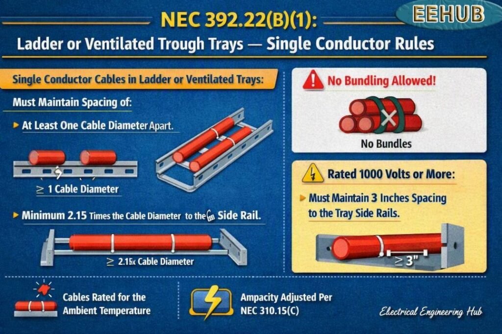
Table of Contents
Table of Contents
What Is NEC 392.22(B)(1)?
NEC 392.22(B)(1) establishes the cable fill rule for single-conductor cables installed in ladder or ventilated trough cable trays. The rule is particularly important for installations containing large conductors because the physical size of each conductor can quickly consume the available tray area.
For the applicable cable tray arrangement, the sum of the cross-sectional areas of the single-conductor cables must remain within the permitted percentage of the tray’s usable interior area. The commonly applied maximum is 40%.
This is different from simply counting how many cables can fit inside a tray. The calculation is based on physical cross-sectional area, so a 500 kcmil conductor and a 4/0 conductor cannot be treated as equal-sized cables.
Why the 40% Fill Limit Matters
The 40% limit provides a practical balance between conductor capacity and available space. A cable tray needs enough open area around the conductors for installation, inspection, ventilation, and heat management.
For example, consider a tray with an interior width of 12 inches and a usable depth of 4 inches.
The total interior cross-sectional area is:
12 × 4 = 48 in²
At a 40% maximum fill:
48 × 0.40 = 19.2 in²
Therefore, the combined cross-sectional area of the applicable single conductors should not exceed 19.2 square inches.
This calculation illustrates why tray dimensions must be confirmed before selecting a tray for a large feeder system.
How to Calculate Single-Conductor Cable Tray Fill
A simple calculation can be used to check compliance.
Step 1: Determine the tray area
Multiply the inside width by the usable inside depth.
Tray area = inside width × usable depth
Step 2: Determine conductor area
Use the actual outside diameter of each cable when calculating physical cross-sectional area.
For a round conductor or cable:
Cable area = π × D² ÷ 4
where D is the outside diameter.
Step 3: Add all conductor areas
If the tray contains different cable sizes, calculate each cable group separately and add the results.
Total cable area = Area 1 + Area 2 + Area 3 + …
Step 4: Apply the permitted fill
For the 40% limit:
Maximum cable area = Tray area × 0.40
The total cable area must remain at or below the permitted value.
For a faster design check, use a dedicated nec cable tray fill requirements calculator or reference guide before finalizing the tray dimensions.
Example Calculation
Suppose a ladder tray has an inside width of 18 inches and a usable depth of 6 inches.
The tray area is:
18 × 6 = 108 in²
The maximum area at 40% fill is:
108 × 0.40 = 43.2 in²
Assume the installed single-conductor cables have a combined calculated cross-sectional area of 35 in².
The resulting fill percentage is:
35 ÷ 108 × 100 = 32.4%
Since 32.4% is below the 40% maximum, the arrangement passes the fill-area check under the stated condition.
If the cable area were 45 in², the calculated fill would be:
45 ÷ 108 × 100 = 41.7%
That arrangement would exceed the 40% limit and would require a larger tray or a different cable arrangement.
Ladder Tray vs Ventilated Trough Tray
Both ladder and ventilated trough trays are commonly used for power distribution, but their construction differs.
| Feature | Ladder Tray | Ventilated Trough Tray |
|---|---|---|
| Construction | Side rails with rungs | Continuous bottom with ventilation openings |
| Air movement | Excellent | Good |
| Cable support | Rungs | Ventilated bottom |
| Common use | Large power cables | Power and control installations |
| Cable access | Easy | Generally easy |
| Heat dissipation | Very good | Good |
| Fill calculation | Area-based | Area-based |
The tray style does not remove the need to perform the applicable conductor-fill calculation. Tray dimensions, conductor diameter, conductor arrangement, and installation conditions must all be considered.
Important Considerations for Large Single Conductors
Large conductors deserve additional attention because their diameter can vary considerably between manufacturers. Two cables with the same electrical rating may have different outside diameters because of insulation thickness, conductor construction, shielding, or jacket design.
Always use the manufacturer’s published dimensions when calculating physical cable fill.
Other factors include:
- Cable insulation type
- Conductor material
- Actual outside diameter
- Number of parallel conductors
- Tray width and depth
- Ambient temperature
- Cable spacing
- Circuit loading
- Voltage level
- Installation environment
The ampacity calculation is separate from the physical tray-fill calculation. A cable can satisfy its ampacity requirement while the selected tray still fails the physical fill requirement.
Parallel Conductors and Tray Layout
Large feeders often use parallel conductors to carry high current. When multiple conductors are installed in parallel, the physical area of every conductor must be considered.
For example, a three-phase feeder may use several parallel sets of 500 kcmil copper conductors. The tray designer must account for every conductor occupying the tray, not merely the number of circuits.
Good cable arrangement also matters. Conductors should be installed in a practical configuration that allows safe installation and future maintenance.
Where several circuits share the same tray, verify the applicable NEC requirements for conductor grouping, spacing, ampacity adjustment, grounding conductors, and circuit arrangement.
For a broader overview of tray sizing, conductor spacing, and fill calculations, see our guide to nec cable tray fill requirements before selecting the final tray size.
Common Mistakes to Avoid
Several mistakes can lead to an incorrect cable tray design.
Using nominal conductor size instead of actual diameter
A conductor marked 500 kcmil does not directly provide its physical outside diameter. Manufacturer data should be used for accurate fill calculations.
Ignoring parallel conductors
Every conductor physically installed in the tray contributes to the total occupied area.
Confusing ampacity with fill
Ampacity tells you how much current a conductor can safely carry under specified conditions. Cable tray fill determines how much physical cable area can occupy the tray.
Measuring the wrong tray dimensions
Use the usable interior dimensions rather than relying only on the tray’s nominal trade size.
Forgetting future cables
If the tray is expected to accommodate future feeders, the design should account for the intended expansion rather than sizing the tray only for today’s cables.
Cable Tray Fill and Ampacity Are Different Checks
A complete design normally requires several independent checks.
| Design check | What it determines |
|---|---|
| Cable tray fill | Physical space occupied by cables |
| Conductor ampacity | Allowable current |
| Voltage drop | Performance over conductor length |
| Temperature correction | Effect of ambient conditions |
| Adjustment factors | Effect of multiple current-carrying conductors |
| Short-circuit rating | Ability to withstand fault conditions |
| Mechanical loading | Tray structural capacity |
| Support spacing | Required tray support arrangement |
Passing the fill calculation does not automatically mean the entire installation complies with the NEC.
Practical Design Tips
When designing a ladder or ventilated trough tray for single-conductor feeders, start with the actual cable manufacturer’s dimensions. Calculate the total cross-sectional area and compare it with the permitted tray area.
It is also good practice to avoid designing a tray right at its maximum theoretical capacity. A larger tray may provide easier cable installation, better maintenance access, and more room for future circuits.
For projects involving several large feeders, prepare a cable schedule containing conductor size, insulation type, outside diameter, quantity, and calculated area. This makes the design easier to review and update.
Before construction, verify the selected cable tray, conductor arrangement, ampacity calculations, and installation details against the NEC edition adopted by the local authority having jurisdiction.
Final Takeaway
NEC 392.22(B)(1) provides an important physical cable-fill requirement for single-conductor cables installed in ladder or ventilated trough cable trays. The 40% area limit is a key value for the applicable installation and should be calculated using the actual cable dimensions and usable tray area.
A proper design should not stop at the fill calculation. Conductor ampacity, spacing, temperature effects, parallel conductors, voltage drop, mechanical loading, and local code requirements should also be reviewed.
If you are sizing a tray for multiple power feeders, our detailed nec cable tray fill requirements guide can help you compare tray dimensions, conductor areas, and allowable fill before selecting the final cable tray.
Frequently Asked Questions
1. What does NEC 392.22(B)(1) cover?
NEC 392.22(B)(1) covers the permitted cable area for single-conductor cables installed in the applicable ladder or ventilated trough cable tray configurations. The calculation is based on the combined physical cross-sectional area of the conductors.
2. What is the maximum cable tray fill for single conductors?
For the installation covered by this rule, the commonly applied maximum is 40% of the usable interior cross-sectional area of the cable tray. Always verify the exact NEC edition and applicable subsection for the project.
3. Does conductor ampacity determine cable tray fill?
No. Ampacity and tray fill are separate calculations. Ampacity determines the allowable current under specified conditions, while tray fill determines the physical amount of cable that can occupy the tray.
4. Can different conductor sizes be installed in the same ladder tray?
Yes, where the installation meets all applicable NEC requirements. When different sizes are used, calculate the physical area contributed by each conductor and add those areas to determine the total tray occupancy.
5. Should actual cable diameter be used for tray-fill calculations?
Yes. The manufacturer’s actual outside diameter is the best basis for physical fill calculations. Using only the conductor’s kcmil or AWG designation can produce an inaccurate estimate because cable construction and insulation dimensions vary.
Get new guides in your feed. Follow Electrical Insights on LinkedIn for new electrical standards guides, calculators and design tips from Azad Circuit Hub.
#NEC39222B1, #CableTray, #ElectricalCode, #NEC, #SingleConductors, #LadderTray, #VentilatedTrough, #ElectricalInstallation, #CableManagement, #ElectricalEngineering