
Insulation Resistance Testing Procedures: Complete Guide
Insulation resistance testing is a key electrical maintenance practice used to check the condition of cable insulation, windings, motors, transformers, switchgear, and other electrical equipment. A good test can identify moisture, contamination, aging, mechanical damage, and insulation breakdown before they cause an electrical fault.
Following proper Insulation Resistance Testing Procedures is important because the test result depends on more than simply connecting a megohmmeter and taking a reading. The correct test voltage, equipment condition, temperature, test duration, and connection method all affect the final result.
This guide explains how to perform the test safely, how to interpret readings, and which factors should be considered when evaluating insulation resistance.
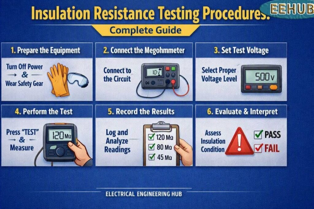
Table of Contents
Table of Contents
What Is Insulation Resistance Testing?
Insulation resistance testing measures the resistance between an electrical conductor and ground, or between two isolated conductors. The measurement is normally expressed in megohms (MΩ), although healthy insulation can produce readings in the gigohm range.
A megohmmeter, commonly called a Megger, applies a controlled DC test voltage to the insulation. The instrument measures the resulting leakage current and calculates resistance using Ohm’s law.
Higher resistance generally indicates better insulation condition, while a low or rapidly decreasing reading may indicate moisture, dirt, deterioration, or physical damage.
Why Insulation Resistance Testing Is Important
Electrical insulation naturally deteriorates with age and exposure to heat, moisture, chemicals, vibration, and electrical stress. Regular testing provides a practical way to monitor this deterioration.
The main benefits include:
- Detecting insulation deterioration before failure
- Identifying moisture or contamination
- Checking newly installed cables and equipment
- Verifying insulation after maintenance or repair
- Reducing unexpected equipment downtime
- Supporting preventive and predictive maintenance
- Providing historical test data for condition monitoring
For installations where standards compliance is important, reviewing the iec standard for insulation resistance test can also help determine the appropriate testing approach and acceptance criteria.
Equipment Required for the Test
A suitable insulation resistance test requires more than a test instrument. The equipment under test must be isolated, discharged, and prepared correctly.
| Equipment | Purpose |
|---|---|
| Insulation resistance tester | Applies DC voltage and measures insulation resistance |
| Test leads | Connect the tester to conductors and ground |
| PPE | Protects personnel from electrical hazards |
| Lockout/tagout equipment | Prevents accidental energization |
| Multimeter | Helps verify that the circuit is de-energized |
| Temperature/humidity meter | Records environmental conditions |
| Cleaning materials | Remove surface dirt and contamination |
Modern insulation testers may provide selectable test voltages such as 250 V, 500 V, 1,000 V, 2,500 V, and 5,000 V. The correct voltage must always be selected according to the equipment, system voltage, and applicable standard.
Preparation Before Insulation Resistance Testing
Proper preparation is one of the most important parts of Insulation Resistance Testing Procedures. Never begin by connecting a tester to an unknown or energized circuit.
Follow these steps:
- Identify the equipment or circuit being tested.
- Isolate it from every possible power source.
- Apply an appropriate lockout/tagout procedure.
- Verify the absence of voltage with a suitable meter.
- Disconnect sensitive electronic devices if required.
- Inspect cables, terminals, and insulation for visible damage.
- Clean excessive dirt, dust, oil, or moisture from test points.
- Record ambient temperature and humidity.
- Confirm that the selected test voltage is suitable.
- Make sure the equipment has no stored electrical energy.
Electronic controls, variable frequency drives, surge protection devices, PLC inputs, and other sensitive components may require isolation before applying a high DC test voltage.
Step-by-Step Insulation Resistance Testing Procedures
Once the equipment is safely isolated, the test can be performed systematically.
Step 1: Verify the Circuit Is De-Energized
Use an approved voltage tester or multimeter to confirm that no hazardous voltage remains. Do not rely only on the position of a circuit breaker or disconnect switch.
Step 2: Select the Test Voltage
Choose the test voltage based on the equipment manufacturer’s instructions and the applicable electrical standard. Applying an unnecessarily high voltage can damage components that are not designed for that test.
Step 3: Connect the Test Leads
For a cable, one lead is normally connected to the conductor under test and the other to ground or another conductor.
For multi-core cables, each core may be tested against the remaining cores and earth, depending on the test plan.
Step 4: Apply the Test Voltage
Start the test and allow the insulation resistance value to stabilize. Many digital testers display resistance automatically, while some provide additional measurements such as leakage current and polarization index.
Step 5: Record the Reading
Record the measured resistance along with:
- Test voltage
- Test duration
- Equipment identification
- Ambient temperature
- Humidity
- Connection arrangement
- Previous test result
This information makes future condition comparisons much more useful.
Step 6: Discharge the Equipment
After the test, stop the test voltage and allow the equipment to discharge through the tester. Large cables and electrical equipment can retain a dangerous charge after testing.
Never touch the test terminals immediately after completing a high-voltage insulation test. Read our complete guide on how to test insulation resistance.
Insulation Resistance Test of Transformer
An insulation resistance test of transformer windings checks the condition of insulation between windings and ground. As part of standard Insulation Resistance Testing Procedures, a megohmmeter applies DC voltage and measures leakage resistance. Before testing, isolate the transformer, discharge it, and verify it is de-energized.
| Test | Typical Connection |
|---|---|
| HV to LV | HV winding to LV winding |
| HV to Ground | HV winding to tank/ground |
| LV to Ground | LV winding to tank/ground |
Record readings at consistent test voltages and compare them with previous results or manufacturer guidance. A declining resistance value can indicate moisture, contamination, aging, or insulation damage.
For a detailed step-by-step approach, follow this insulation resistance test of transformer guide to ensure safe connections, testing, and result interpretation.
Typical Test Voltage and Resistance Guide
The correct acceptance value depends on the equipment and governing standard. The following table is a general reference, not a universal pass/fail table.
| Application | Common Test Voltage | General Interpretation |
|---|---|---|
| Low-voltage circuits | 250–500 V DC | Higher resistance is normally desirable |
| 480 V equipment | 500–1,000 V DC | Compare with manufacturer requirements |
| Motors | 500–1,000 V DC | Consider winding temperature |
| Medium-voltage cables | 2,500–5,000 V DC | Follow cable and test standard |
| Control wiring | Often 250–500 V DC | Isolate sensitive electronics |
A resistance value should never be judged without considering equipment type, temperature, test voltage, and historical results.
How to Megger Test a 3 Phase Motor
Learning how to megger test a 3 phase motor helps identify weak insulation before it causes winding failure or an electrical fault. As part of standard Insulation Resistance Testing Procedures, disconnect and isolate the motor, then verify it is de-energized.
| Test | Connection | Purpose |
|---|---|---|
| Phase-to-ground | Winding to motor frame | Checks insulation to earth |
| Phase-to-phase | One winding to another | Detects winding insulation weakness |
Apply the appropriate DC test voltage with a calibrated insulation resistance tester and record the reading. Compare results between phases and against the motor manufacturer’s guidance. A significantly lower or unbalanced reading warrants further investigation before energizing the motor. Always discharge the windings safely after testing because they can retain a dangerous charge.
For the complete procedure, see this guide on how to megger test a 3 phase motor.
How to Interpret Insulation Resistance Results
A single high reading is useful, but trending is often more valuable. If a motor consistently measures 500 MΩ and later drops to 50 MΩ, the change deserves investigation even if 50 MΩ may appear acceptable for a particular application.
Low resistance can result from:
- Moisture absorption
- Dirty insulation surfaces
- Aging insulation
- Carbon tracking
- Cracks or physical damage
- Excessive operating temperature
- Chemical contamination
- Poor terminations
- Internal winding deterioration
Temperature also has a major effect on insulation resistance. As insulation temperature increases, resistance generally decreases. For this reason, test results should be recorded with temperature and, where applicable, corrected or compared under similar conditions.
For projects requiring formal compliance, consult the iec standard for insulation resistance test applicable to the specific equipment and installation rather than relying on a generic resistance threshold.
Polarization Index and Dielectric Absorption Ratio
For motors, generators, and other larger electrical equipment, additional diagnostic tests can provide more information than a single resistance reading.
The Polarization Index (PI) compares insulation resistance at two different test times, commonly 10 minutes and 1 minute:
PI = 10-minute resistance ÷ 1-minute resistance
The Dielectric Absorption Ratio (DAR) uses a shorter time comparison, commonly involving readings at 60 seconds and 30 seconds.
These tests can help identify insulation conditions that may not be obvious from a single measurement. However, interpretation should follow the equipment manufacturer’s instructions and the applicable testing standard.
Common Testing Mistakes to Avoid
Poor test practices can produce misleading readings or create safety hazards.
| Mistake | Possible Problem |
|---|---|
| Testing an energized circuit | Severe shock or arc-flash hazard |
| Using excessive test voltage | Possible component damage |
| Ignoring temperature | Incorrect comparison of readings |
| Skipping discharge | Stored electrical energy remains |
| Testing through electronic devices | Equipment damage |
| Not recording historical results | Poor condition trending |
| Dirty test points | Artificially low readings |
| Loose test connections | Unstable or inaccurate measurements |
When developing a maintenance procedure, using the iec standard for insulation resistance test as a reference can help align the test method with the requirements relevant to the equipment.
Insulation Resistance Testing for Cables and Motors
Cable testing usually involves checking each conductor against earth and, where required, between conductors. Cable ends should be isolated from connected equipment that could be affected by the applied DC voltage.
Motor insulation testing commonly checks winding-to-ground insulation. Depending on the motor design and maintenance program, phase-to-phase tests may also be performed.
Before testing a motor, disconnect it from drives, starters, control equipment, and other devices that are not intended to receive the test voltage.
Best Practices for Reliable Test Results
Follow these practices to improve accuracy and repeatability:
- Use a calibrated insulation resistance tester.
- Follow the equipment manufacturer’s instructions.
- Keep test connections clean and secure.
- Record temperature and humidity.
- Use consistent test durations.
- Compare results with previous measurements.
- Investigate significant downward trends.
- Discharge equipment after every test.
- Keep sensitive electronic components isolated.
- Document every test in the maintenance record.
A good maintenance program focuses on trends rather than treating every reading as an isolated pass or fail result.
Safety Precautions
Insulation resistance testing involves potentially hazardous DC voltages. Only trained and authorized personnel should perform these tests.
Always isolate the equipment, verify zero energy, use appropriate PPE, control access to the test area, and follow site electrical safety procedures. After testing, discharge the equipment before removing leads.
Never assume that a circuit is safe simply because the tester is no longer applying voltage. Capacitive equipment and long cables can retain electrical charge.
Frequently Asked Questions
1. What is a good insulation resistance reading?
There is no single value that applies to every electrical system. A good reading depends on equipment type, voltage rating, temperature, manufacturer requirements, and applicable standards. High and stable resistance is generally desirable.
2. What voltage is used for an insulation resistance test?
Common test voltages include 250 V, 500 V, 1,000 V, 2,500 V, and 5,000 V DC. The correct selection depends on the equipment and testing requirements. Always follow the manufacturer’s instructions before selecting the test voltage.
3. How long should an insulation resistance test be performed?
A basic test may be performed for around 60 seconds, while diagnostic tests such as PI use longer test periods. The required duration depends on the equipment and the purpose of the test.
4. Can insulation resistance testing damage electrical equipment?
It can if the wrong test voltage is applied to sensitive components. Electronic equipment, drives, control systems, and surge protection devices may need to be disconnected before testing.
5. Why does insulation resistance decrease with temperature?
Higher insulation temperature generally increases leakage current and reduces measured resistance. This is why temperature should be recorded during testing and why comparisons should consider temperature differences.
Related Guides
Final Thoughts
Proper Insulation Resistance Testing Procedures provide valuable information about the electrical health of cables, motors, transformers, switchgear, and other equipment. The most useful results come from safe preparation, correct test voltage selection, consistent testing methods, accurate documentation, and comparison with previous readings.
For engineers and maintenance teams working with formal electrical testing requirements, reviewing the iec standard for insulation resistance test alongside manufacturer documentation provides a stronger basis for selecting test methods and evaluating results. Regular testing can reveal insulation deterioration early, helping prevent unexpected failures and costly downtime.
Get new guides in your feed. Follow Electrical Insights on LinkedIn for new electrical standards guides, calculators and design tips from Azad Circuit Hub.
#InsulationResistanceTesting, #InsulationTesting, #MeggerTesting, #ElectricalTesting, #ElectricalSafety, #CableTesting, #MotorTesting, #ElectricalMaintenance, #IECStandards, #ElectricalEngineering
