
IEC Standard for Insulation Resistance Test(Megger Testing)
The IEC standard for insulation resistance test plays a critical role in ensuring electrical safety, system reliability, and long-term equipment performance. Insulation resistance testing is one of the most widely used diagnostic methods in electrical engineering, applied to cables, motors, transformers, switchgear, and industrial installations. International Electrotechnical Commission (IEC) standards provide globally accepted procedures and limits that help engineers assess insulation health accurately.
This article explains the IEC standard for insulation resistance test in detail, covering applicable standards, testing procedures, acceptable limits, influencing factors, and best practices followed by professionals in the field.
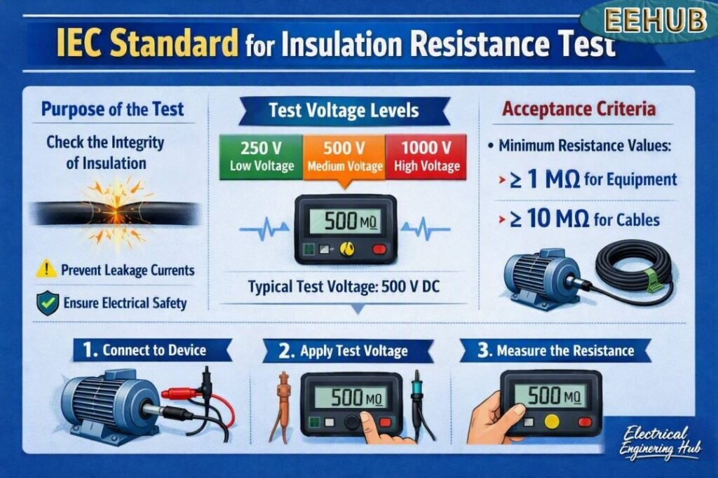
Table of Contents
Table of Contents
What Is Insulation Resistance Testing
Insulation resistance testing measures the resistance offered by insulating materials against leakage current. A DC voltage is applied between conductors or between conductor and earth, and the resulting resistance is measured in megaohms (MΩ) or gigaohms (GΩ).
The IEC standard for insulation resistance test ensures that measurements are consistent, repeatable, and safe, regardless of equipment type or voltage class.
Key objectives of insulation resistance testing include:
- Detecting insulation deterioration
- Preventing electric shock hazards
- Reducing risk of fire and equipment failure
- Verifying installation quality
- Supporting preventive maintenance programs
Read our complete guide on Insulation Resistance Test here.
IEC Standards Applicable to Insulation Resistance Testing
Several IEC documents define requirements and guidance for insulation resistance measurement. The IEC standard for insulation resistance test is not limited to one document but covered across multiple standards depending on equipment type.
The most commonly referenced IEC standards are listed below.
| IEC Standard | Scope |
|---|---|
| IEC 60364-6 | Verification of low-voltage electrical installations |
| IEC 60034-1 | Rotating electrical machines |
| IEC 60502 | Power cables with extruded insulation |
| IEC 60204-1 | Electrical equipment of machines |
| IEC 61800-5-1 | Adjustable speed electrical power drive systems |
| IEC 61557-2 | Insulation resistance measuring instruments |
These standards collectively define how the IEC standard for insulation resistance test should be applied in practical scenarios.
For a deeper understanding of test requirements, voltage levels, and acceptable practices, explore our complete guide to Insulation Resistance Testing Standards.
IEC Standard for Megger Test Explained
The IEC standard for Megger test primarily refers to the guidelines outlined in IEC 60060, IEC 60085, and IEC 61557-2. These international standards define procedures for testing insulation resistance, ensuring uniformity across various types of electrical equipment.
The IEC 61557-2 standard specifically addresses insulation resistance measurement for low-voltage electrical installations. It defines test voltages, measurement ranges, and accuracy requirements for insulation testers.
The IEC 60085 standard focuses on the thermal evaluation and classification of electrical insulation systems. It relates to how insulation performance changes under temperature stress, which is a key factor in the reliability of Megger test results.
The IEC 60060 standard covers high-voltage testing techniques, including the insulation testing of power cables and transformers. It helps ensure that test voltages and procedures do not damage insulation during testing.
Together, these standards create a framework for performing insulation resistance tests in a safe and reliable manner.
Test Equipment as Per IEC Requirements
The IEC specifies the use of insulation resistance testers, commonly known as megohmmeters or megger testers. According to the IEC standard for insulation resistance test, test instruments must meet accuracy and safety requirements defined in IEC 61557-2.
Common test voltages recommended by IEC include:
- 250 V DC
- 500 V DC
- 1000 V DC
- 2500 V DC
- 5000 V DC
Selection of test voltage depends on system rated voltage and insulation class.
IEC Recommended Test Voltages and Limits
The IEC standard for insulation resistance test provides guidance on minimum acceptable resistance values based on system voltage.
| System Voltage | Test Voltage (DC) | Minimum Insulation Resistance |
|---|---|---|
| ≤ 50 V | 250 V | 0.5 MΩ |
| 50 V – 500 V | 500 V | 1 MΩ |
| 500 V – 1000 V | 1000 V | 1 MΩ |
| > 1 kV | As per manufacturer | As specified |
These limits are general guidelines. Equipment-specific IEC standards may define higher thresholds.
Insulation Resistance Testing Procedures
Following the IEC standard for insulation resistance test, the procedure should be systematic and documented.
Pre-Test Safety Checks
- Isolate and lock out the equipment
- Discharge stored energy in capacitors
- Disconnect sensitive electronics
- Verify absence of voltage
- Ensure correct PPE usage
| Test Step | Key Action |
|---|---|
| Isolate | Disconnect and de-energize the circuit |
| Inspect | Check cables, terminals, and insulation |
| Connect | Attach the insulation resistance tester correctly |
| Test | Apply the specified DC test voltage |
| Record | Document readings and test conditions |
The IEC standard for insulation resistance test typically recommends a minimum test duration of 60 seconds for stable readings. For reliable results, discharge the circuit after testing and compare readings with applicable equipment and installation requirements. Temperature, moisture, and cable length can affect resistance values.
For a detailed step-by-step guide, see these Insulation Resistance Testing Procedures to understand practical testing methods and result interpretation.
Procedure for Megger Test as per IEC
The IEC standard for Megger test outlines a systematic procedure to ensure accurate and repeatable results. The process can be summarized as follows:
- Preparation – Disconnect the equipment from the power supply and discharge any residual voltage to prevent damage or injury.
- Cleaning and Inspection – Check for dust, oil, or moisture on terminals and insulation surfaces, as these can affect the reading.
- Connection – Connect the Megger leads: one to the conductor under test and the other to the equipment’s body or earth.
- Voltage Application – Apply the appropriate DC voltage as per IEC guidelines for one minute.
- Reading and Interpretation – Record the insulation resistance value displayed on the Megger.
- Polarization Index (PI) Test – Optionally, measure resistance at 1 minute and 10 minutes to calculate PI (10 min/1 min). A PI value above 2 indicates good insulation.
- Post-Test Discharge – Discharge the tested insulation to ground after the test to remove stored charge.
This procedure ensures repeatable and safe measurement under standardized conditions.
Factors Affecting Insulation Resistance Values
Insulation resistance readings are influenced by several environmental and operational factors. IEC emphasizes consideration of these variables during evaluation.
Key influencing factors include:
- Temperature of insulation
- Humidity and moisture presence
- Surface contamination
- Insulation aging
- Cable length and geometry
The IEC standard for insulation resistance test advises temperature correction when comparing readings taken at different times.
Polarization Index and Dielectric Absorption Ratio
While basic insulation resistance is useful, IEC standards also recognize time-based diagnostic ratios.
Polarization Index (PI)
PI is the ratio of insulation resistance at 10 minutes to 1 minute.
PI = IR at 10 min ÷ IR at 1 min
Typical interpretation:
| PI Value | Insulation Condition |
|---|---|
| < 1 | Poor |
| 1 – 2 | Questionable |
| 2 – 4 | Good |
| > 4 | Excellent |
Need to verify insulation resistance test requirements? Our detailed Insulation Resistance Testing Standards guide covers the key standards and testing practices you should know.
Dielectric Absorption Ratio (DAR)
DAR compares resistance at 60 seconds and 30 seconds. The IEC standard for insulation resistance test recognizes DAR mainly for rotating machines and transformers.
Insulation Resistance Testing for Different Equipment
The IEC standard for insulation resistance test applies differently based on equipment type.
Cables and Wiring
- Test between phases
- Test phase to earth
- Longer cables naturally show lower resistance
Motors and Generators
- Test stator windings to earth
- Follow IEC 60034 guidance
- Consider PI values for condition assessment
Transformers
- Test HV to LV, HV to earth, LV to earth
- Consider temperature correction
- Follow manufacturer and IEC limits
Switchgear and Panels
- Ensure electronic components are isolated
- Test busbars and insulation barriers
- Verify post-installation compliance
Interpretation of Results as per IEC
The IEC standard for Megger test provides general acceptance criteria, but actual acceptable limits often depend on equipment type and manufacturer recommendations. However, IEC suggests some general guidelines:
| Insulation Resistance (MΩ) | Condition Assessment |
|---|---|
| Above 100 MΩ | Excellent insulation |
| 10 MΩ to 100 MΩ | Good, within safe limits |
| 1 MΩ to 10 MΩ | Acceptable but monitor |
| Below 1 MΩ | Poor, needs immediate action |
A sudden drop in insulation resistance over time is a warning sign that insulation deterioration is occurring. Regular trend analysis is more valuable than relying on a single measurement.
Advantages of Following IEC Standard
Adhering to the IEC standard for Megger test brings several benefits for electrical maintenance and safety programs.
- Global Consistency – Results are comparable across different countries and industries.
- Safety Assurance – Ensures test voltage and methods do not endanger personnel or equipment.
- Accuracy and Repeatability – Standardized procedures produce reliable measurements.
- Predictive Maintenance – Helps identify insulation aging before failures occur.
- Regulatory Compliance – Satisfies inspection and certification requirements for international projects.
For industries such as power generation, oil and gas, and manufacturing, following IEC standards is essential for operational reliability and global compliance.
Applications of Megger Test
The IEC standard for Megger test applies to a wide range of electrical equipment. Some common applications include:
- Power Cables – Checking insulation between conductors and earth.
- Motors and Generators – Evaluating winding insulation before commissioning or after maintenance.
- Transformers – Measuring insulation between windings and core.
- Switchgear and Circuit Breakers – Ensuring dielectric integrity before energization.
- Control Panels – Verifying insulation resistance of wiring circuits.
Regular testing under IEC guidelines enhances system reliability and extends equipment lif
Common Mistakes to Avoid
Despite clear guidance from the IEC standard for insulation resistance test, errors are common in field testing.
Avoid the following mistakes:
- Testing without isolating electronic devices
- Using incorrect test voltage
- Ignoring temperature effects
- Recording unstable readings
- Skipping post-test discharge
Proper training and adherence to IEC procedures reduce false failures and safety risks.
Best Practices Recommended by IEC
Experienced engineers follow several best practices aligned with the IEC standard for insulation resistance test.
- Maintain historical test records
- Use the same test voltage for trend analysis
- Perform tests under similar environmental conditions
- Combine IR testing with visual inspection
- Do not rely on resistance value alone
Consistent documentation enhances reliability-centered maintenance programs.
Why IEC Compliance Matters
Compliance with the IEC standard for insulation resistance test ensures international acceptance of test results. It also improves safety audits, regulatory inspections, and equipment warranty compliance.
IEC-based testing supports:
- Reduced downtime
- Early fault detection
- Improved asset life
- Safer electrical installations
- Globally standardized practices
Conclusion
The IEC standard for insulation resistance test provides a structured, reliable, and globally accepted approach to evaluating insulation health in electrical systems. By understanding applicable standards, recommended limits, testing procedures, and best practices, engineers can make informed maintenance decisions and ensure system safety.
When performed correctly and consistently, insulation resistance testing becomes a powerful preventive tool rather than a simple pass-or-fail measurement. Adhering to IEC guidelines not only protects equipment but also safeguards personnel and operational continuity.
Follow Us on Social:
Subscribe our Newsletter on Electrical Insights for latest updates from Azad Circuit Hub
#IECStandard,#InsulationResistanceTest,#IECTestingStandards,#ElectricalSafetyTesting,#IRTestProcedure,#ElectricalCompliance,#CableTesting,#ElectricalEngineering,#PowerSystemTesting,#IECGuidelines
